

LED Theory: Basic Concepts
Some basic theory about LEDs (Light Emitting Diodes) for anyone interested in exploring in more detail the theoretical aspects mentioned in the videos of the LED series [Link to LED video tag].
An LED is a p-n junction diode capable of emitting light when current flows through it under forward bias. In practice, electrons and holes recombine at the junction, releasing energy in the form of photons (light).
Semiconductors
Energy bands in a semiconductor
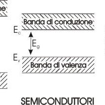
In a semiconductor, the energy difference between the conduction band and the valence band, known as the energy gap or band gap (Eg), is small enough to allow some electrons to move from the valence band, where they are abundant, to the conduction band, where they are much less numerous. This transfer leaves vacancies in the valence band, corresponding to missing electrons. These vacancies behave as positive charge carriers known as holes. At the same time, an excess of negative charge carriers is present in the conduction band. When an electric field is applied to the semiconductor, both conduction-band electrons and valence-band holes can move, producing a net electric current.
Semiconductors can be modified by introducing atoms of different elements, a process known as doping. If atoms with more valence electrons than the host semiconductor are introduced, an N-type material is obtained, with an excess of electrons acting as negative charge carriers. Conversely, introducing atoms with fewer valence electrons produces a P-type material, with an excess of holes acting as positive charge carriers.
Diodes, including LEDs, contain a PN junction, formed by an N-type region associated with the cathode and a P-type region associated with the anode. At the junction between these regions, charge carriers of opposite sign interact: holes in the P-type material and electrons in the N-type material. When an electron recombines with a hole, excess energy is released. In LEDs, this energy is emitted as electromagnetic radiation, which may be visible light, infrared radiation, or ultraviolet radiation depending on the band gap of the semiconductor material.
The color emitted by an LED therefore depends mainly on the semiconductor material and its electronic structure. These determine the energy difference between the conduction and valence bands, known as the band gap.
As a result, red LEDs typically have a forward voltage of around ~1.8 V, whereas blue and white LEDs, the latter generally using a blue chip coated with a phosphor layer, require higher voltages, often above 3 V.
The following values provide an approximate indication of the forward voltage between anode and cathode for LEDs of different colors:
- Infrared: ~1.3 V
- Red: ~1.8 V
- Orange / Yellow: ~1.9–2.0 V
- Green: ~2.0 V
- Blue / White: ~3.0–3.5 V
- Ultraviolet: ~4.0–4.5 V
In addition to the semiconductor material, several factors influence the forward voltage of an LED. The main ones include:
- Junction Temperature: the forward voltage of an LED decreases as temperature increases. A reduction of around 2 mV/°C is typical for many devices. Therefore, at constant current, an increase in temperature causes the voltage across the LED to decrease. In constant-voltage circuits this may cause the current to increase, potentially damaging the device if the current is not properly controlled.
- Operating Current: forward voltage varies with the applied current. Higher currents generally correspond to a somewhat higher forward voltage. However, increasing the current beyond the specified limits can overheat the LED, reducing both efficiency and lifetime.
- Series Resistance: every LED has some internal series resistance due to the resistivity of the semiconductor materials, contacts, and interconnections. This resistance contributes to the total voltage drop across the LED, particularly at high currents, producing an additional voltage drop and potentially reducing efficiency.
- Aging and Degradation: prolonged operation can change the electrical characteristics of an LED, including its forward voltage. Phenomena such as electromigration and the formation of internal defects may increase series resistance and modify the voltage required for operation.
A fundamental characteristic of an LED, like any diode, is its nonlinear behavior: below a certain voltage almost no current flows, while above the apparent “threshold” the current rises very rapidly. It is therefore essential to control the current flowing through an LED rather than simply applying a fixed voltage.
The voltage drop across a conducting LED changes relatively little compared with the current, so a small change in voltage can produce a large change in current.
For this reason, supplying an LED directly from a fixed voltage can be dangerous. A small voltage error or an increase in temperature can cause the current to rise excessively and damage the device. In other words, an LED does not limit its own current: once conducting, its voltage remains approximately in the 2–3 V range depending on the device, and without an external current-limiting element the current may rise until the LED is damaged.
In practice, an LED must therefore be operated with a controlled current: the driver circuit must ensure that the desired current flows, for example 10 mA, while the LED assumes the corresponding forward voltage.
The simplest method is to place a series resistor in the LED circuit when using a low-voltage supply. For power LEDs, a dedicated constant-current driver is normally used.
For example, if a red LED with Vf ≈ 1.8 V is connected to a 9 V battery and a current of 15 mA is required, the series resistor can be calculated using Ohm’s law: R = (Vsupply – VLED) / ILED. Therefore R ≈ (9 – 1.8) / 0.015 ≈ 480 Ω.
The resistor drops the remaining voltage and limits the current. In microcontroller circuits, for example with a 5 V output, resistors around ~220 Ω are often used with indicator LEDs, resulting in currents of approximately 10–20 mA depending on the LED forward voltage and the output characteristics.
It is important to remember, however, that a microcontroller is not designed to supply high currents: its digital outputs can provide only a limited amount of current. For example, with the ATmega328P, used in many Arduino boards, 20 mA per pin is a commonly recommended operating value, while the absolute maximum total current through the device is approximately 200 mA, with additional limits applying to groups of pins as specified in the datasheet. The absolute maximum current for an individual pin is 40 mA, but this value should not be considered a normal continuous operating current.
Therefore, when several LEDs or other loads are driven simultaneously from different pins, the total current capability of the MCU can be exceeded. For this reason, it is good practice to use external switching devices such as BJTs, MOSFETs, or dedicated drivers for larger loads, avoiding excessive stress on the microcontroller outputs.
For high-power LEDs, for example devices rated at 1 W or more, a simple series resistor becomes inefficient because it may dissipate significant power. In these applications, switching constant-current drivers are normally used to provide the required current with lower power losses.
LED I-V Characteristic and Dynamic Resistance
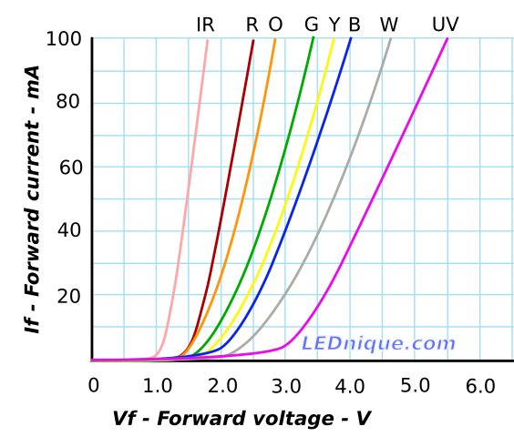
The current-voltage characteristic (I-V curve) of an LED is typical of a semiconductor diode: very little current flows at low forward voltage, followed by a steep, approximately exponential increase in current as the applied voltage rises.
Unlike a resistor, which follows the linear relationship V = R·I, an LED behaves almost like an open circuit at low forward voltage, while its current rises rapidly once the conducting region of the curve is reached. In practical terms, small changes in voltage can produce large changes in current.
This behavior can be described using the dynamic resistance, also known as differential resistance, of the diode. It is defined as dV/dI at a particular operating point on the I-V curve.
In simple terms, it represents the effective small-signal resistance of the LED to small changes in current around a given operating point.
As an intuitive example, consider a red LED with approximately 1.8 V across it at 10 mA. If the current increases to 20 mA, the voltage might rise only to approximately 2.0 V. A current increase of 10 mA has therefore produced a voltage increase of only 0.2 V, corresponding to an average differential resistance of roughly 20 Ω over that interval. At higher currents the I-V curve can become even steeper and the dynamic resistance may fall to only a few ohms.
This means that a conducting LED behaves approximately like a voltage drop with a relatively small differential resistance. Consequently, without external current limiting, a small increase in applied voltage or temperature, which reduces Vf, can produce a large increase in current and potentially damage the device.
The figure shows an example of typical I-V curves for LEDs of different colors. Each LED type — IR = infrared, R = red, O = orange, Y = yellow, G = green, B = blue, W = white, and UV = ultraviolet — has a different forward-voltage characteristic, and once conduction begins the current increases rapidly with the applied voltage.
The figure also illustrates why LEDs should not normally be connected directly in parallel: if two LEDs with different forward voltages are connected across the same voltage, the LED with the lower Vf may conduct most of the current, a phenomenon known as current hogging.
For example, if red, green, and blue LEDs were connected directly in parallel at 2.0 V, the red LED could conduct much more current while the blue LED might remain almost off. For this reason, when LEDs are connected in parallel, each branch should normally have its own current-limiting resistor or current regulator.
In summary, the I-V characteristic must be considered when designing the circuit correctly: each LED branch requires a resistor or constant-current driver, while LEDs connected in series have approximately additive forward voltages and carry the same current.
For example, two LEDs in series with forward voltages of 1.8 V and 2.0 V will have a total forward voltage of approximately 3.8 V at a given current. The operating current must remain within the allowable current rating of both devices.
The interactive box below allows you to explore how the characteristic curve of an LED changes when parameters such as saturation current, temperature, and ideality factor are modified. The saturation current is a very small parameter in the diode equation associated with minority-carrier transport in the semiconductor. It strongly influences the relationship between voltage and current. Although practical LED characteristics are normally obtained from the device datasheet, varying these parameters interactively helps illustrate the behavior of the diode model.
Photon Emission and Efficiency
When an LED conducts in the forward direction, not all of the electrical energy is converted into useful light. Some of the energy is lost as heat through non-radiative processes rather than being emitted as photons.
The internal quantum efficiency of an LED, which represents the fraction of electron-hole recombinations that produce photons, together with the light extraction efficiency, which represents the fraction of generated photons that actually escape from the device, determines how much useful light is produced for a given electrical input.
Modern LEDs can achieve efficiencies far higher than incandescent lamps: for example, a white LED can produce approximately 100–200 lm/W, whereas a traditional incandescent lamp typically produces only around 10–15 lm/W.
However, LED efficiency is not constant as current increases: many LEDs exhibit a reduction in efficiency at high current densities, a phenomenon known as efficiency droop.
In practice, increasing the current beyond a certain point produces a sub-linear increase in emitted light: the LED becomes less efficient and a larger proportion of the input energy is dissipated as heat.
The mechanisms responsible for this phenomenon are complex and can involve several non-radiative recombination processes, including Auger recombination, in which the recombination energy is transferred to another carrier instead of producing a photon. Carrier leakage and other mechanisms can also contribute depending on the LED structure.
In general, to improve efficiency and lifetime, power LEDs are often operated below their absolute maximum rated current. For example, a device rated for 1 A may be operated at 700 mA or less when higher efficiency, lower temperature, and longer lifetime are more important than maximum light output.
Effects of Temperature
Temperature has a significant influence on both the electrical characteristics and the light output of an LED. As mentioned above, increasing the junction temperature generally causes the forward voltage Vf to decrease at a given current.
The negative temperature coefficient dVF/dT depends on the LED technology and operating current. For example, a typical red LED may show a forward-voltage reduction of approximately 80 mV when the junction temperature rises from 25°C to 100°C at relatively low current, with larger changes possible under other operating conditions.
As an approximate rule, the forward-voltage temperature coefficient is typically negative and may be of the order of a few millivolts per degree Celsius, depending on the semiconductor material, LED structure, and operating current.
This means that if an LED is driven directly from a fixed-voltage source, an increase in temperature can increase the current because Vf decreases. This may produce positive thermal feedback: more current → more heating → lower Vf → still more current.
This is another reason why LEDs should be operated using controlled current: the driver adjusts the voltage across the LED as necessary to maintain the required current despite changes in Vf caused by temperature.
From an optical point of view, increasing temperature generally causes the light output at a given current to decrease.
For example, depending on the device, a red LED operating at 80°C may produce only approximately 75–80% of the light output obtained at 25°C for the same current.
The emitted color can also change slightly with temperature. In phosphor-converted white LEDs, variations in chip emission and phosphor conversion efficiency can cause changes in chromaticity as the junction temperature increases.
Manufacturers often specify a derating curve indicating how the maximum allowable current must be reduced as junction temperature increases in order to maintain reliability. High temperatures accelerate degradation mechanisms, causing LEDs to lose light output more rapidly over time.
Proper thermal management is therefore essential. Power LEDs are generally mounted on thermally conductive substrates and coupled to a suitable heatsink. Some drivers also include temperature sensors or thermal-protection functions to prevent excessive junction temperatures.