

Laboratory Diary – A Transistor-Based NE555 as a Test for Giux-CalcLab
These days I am working on Giux-CalcLab, a scientific computing environment that I am developing on my server. The first module I am focusing on is an ngspice-based SPICE simulator, with an editor, server-side simulation management, and a results viewer.
To put it to the test, I wanted something a little more interesting than the usual RC circuit.
The idea was simple: try to reproduce the operation of an NE555 using only discrete components.
Not a SPICE model of the 555, nor a ready-made subcircuit, but NPN and PNP transistors, diodes, resistors, and capacitors.
Download the netlist:
A useful test for the simulator as well
A circuit of this type is interesting because it makes it possible to test several things at the same time:
- custom NPN and PNP transistor models;
- diode models;
- many internal nodes;
- a fairly long transient analysis;
- automatic measurements with
meas; - simultaneous visualization of several quantities;
- handling a netlist significantly more complex than a simple educational example.
The simulation was run on the server and the result was successfully delivered to the new Waveform Viewer.
And this is where the test became more interesting than expected.
First surprise: the circuit does not oscillate
The goal was to obtain the typical behavior of a 555 astable: the timing capacitor should have charged and discharged between two thresholds, causing the internal latch to switch and, consequently, turning the discharge transistor on and off.
The first simulation, however, showed a circuit that was practically stuck.
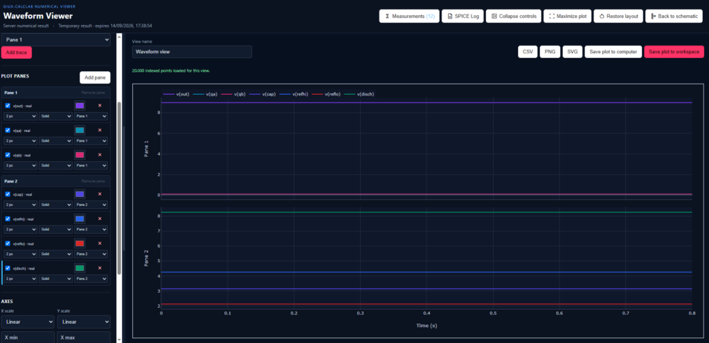
The output remained high and the various internal nodes quickly settled toward constant values.
I therefore separated the signals into two panels in the viewer.
In the first panel I observed the internal logic nodes and the output:
v(OUT)
v(QA)
v(QB)
In the second, the signals related to the comparators and the timing capacitor:
v(CAP)
v(REFHI)
v(REFLO)
v(DISCH)
And it immediately became clear where to look for the problem.
The thresholds were not where they should have been
I had used the classic divider made of three equal resistors, conceptually similar to the one inside the 555.
With a 9 V supply, I would have expected values close to:
- 3 V for the lower threshold;
- 6 V for the upper threshold.
The simulation instead showed much lower values, about 2.1 V and 4.2 V.
The timing capacitor also remained stuck at around 3.1 V, without being able to reach the upper threshold.
The reason is fairly simple: in my first implementation, the transistor stages used as comparators interact too heavily with the nodes they are supposed merely to observe. In particular, the REFHI node is heavily loaded, while the timing capacitor is also affected by the input impedance.
The circuit therefore reaches an equilibrium point:
The capacitor does not reach the upper threshold
↓
The comparator does not switch
↓
The latch remains in the same state
↓
The discharge transistor does not turn on
↓
The output remains high
In other words, the problem was not in the simulator: it was showing me exactly a problem in the circuit.
Even the errors proved useful
The test also revealed some limitations of the current netlist validator.
For security reasons, simulations submitted to the server are checked before execution. The validator is intentionally restrictive, but during this test it became clear that some rules are still too simplistic.
For example, perfectly valid SPICE syntax was initially rejected, including descriptive component and node names, as well as some source and measurement forms.
To continue the test, I temporarily renamed the elements using simple identifiers such as:
R1
R2
Q1
Q2
D1
V1
The validator will need to be improved so that it interprets the syntactic context of the netlist, rather than treating certain words or characters as dangerous regardless of where they appear.
It is one of those problems that probably would not have emerged as easily by using only small circuits prepared specifically as examples.
A real laboratory test, even if virtual
I particularly liked this experiment because it closely reflects the way I normally work at the bench.
You start from an idea, build something, measure its behavior, and often the first result is not the one you expected.
At that point, the wrong result becomes more interesting than the correct one, because it forces you to understand what is happening.
In this case the “bench” was my server, the instruments were ngspice and the waveform viewer, but the procedure was exactly the same.
The next step is therefore to modify the comparator stage to reduce the loading on the reference nodes and on the capacitor, until the expected charge and discharge behavior between approximately 1/3 and 2/3 of the supply voltage is finally obtained.
At that point we will see whether this small discrete 555 finally starts to oscillate.
A second, simpler circuit: the astable multivibrator
The discrete circuit inspired by the 555 therefore still needs to be corrected. In the meantime, to continue testing the simulator with a circuit whose dynamic behavior is easy to recognize, I loaded a second netlist: a classic astable multivibrator built with discrete components.
Download the netlist:
This test is deliberately simpler than the previous attempt with the 555, but it is useful because the expected behavior is very clear: the two branches of the multivibrator must switch alternately and produce easily recognizable periodic waveforms.
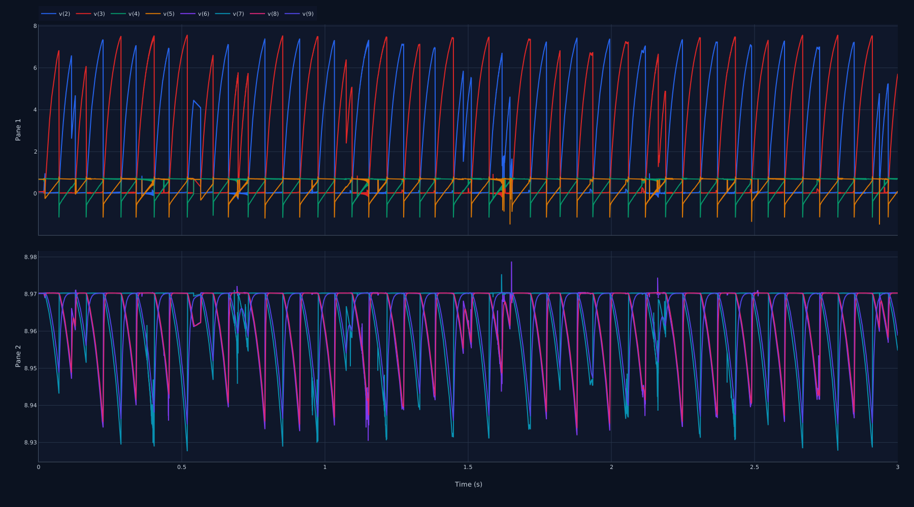
The simulation ran correctly and, this time, the circuit really does oscillate.
Signals displayed in the Waveform Viewer
v(2) and v(3) — collector voltages of the two main transistors of the multivibrator.
v(4) and v(5) — base voltages of the two main transistors, affected by the charging and discharging of the coupling capacitors.
v(6) and v(7) — outputs of the two PNP stages connected to the multivibrator collectors.
v(8) and v(9) — voltages after the respective output RC networks, therefore filtered versions of the signals from the two branches.
Interpretation
Unlike the first circuit inspired by the 555, which tended toward a steady state, here a periodic behavior is immediately visible.
The two main transistors switch alternately: when one conducts, its collector drops toward ground while the opposite collector rises toward the supply voltage. The coupling capacitors rapidly transfer changes from one branch to the other and, together with the bias resistors, determine the time required for the next switching event.
The waveforms of the two branches are therefore essentially complementary, while the base nodes show the characteristic variations caused by capacitor charging and discharging.
This simulation represents a more meaningful test for the system than a simple RC circuit: multiple transistors, NPN and PNP models, diodes, several internal nodes, automatic measurements, and multiple traces distributed across different panels are handled simultaneously.
Conclusion
There is still a considerable amount of work to do, both on the simulator and on the interface, and these tests are revealing several details that need to be corrected and improved.
The important thing, however, is that the project is finally beginning to take shape: simulations are run on the server, results can be analyzed directly in the browser, and the system is getting closer and closer to the original idea.
I hope to reach a sufficiently stable version soon so that I can share it and let others try it as well.