

Zenith Flash-Matic Receiver: Circuit Analysis
The AC line as the photocell excitation source, triggering the 2D21 thyratrons, and driving the motor with the 6BX7GT. A circuit analysis based on Maxwell’s 1956 schematics and Zenith’s technical documentation.
In the Flash-Matic, the light beam changed the impedance of a branch already driven by an AC signal. Zenith used that principle to produce two distinct behaviors. Power and mute needed a pulse that could change the state of a solenoid-operated switch. Channel selection required a relay that stayed energized during the command and a mechanical contact that completed the step after the relay dropped out.
Zenith demonstrated the system in June 1955, with its television range for 1956. Eugene J. Polley’s patent application, filed in May, documents the operating principle and the switch mechanism. The schematics published by Henry O. Maxwell in September 1956 show how Zenith implemented it. The manufacturer’s service manual adds a theory of operation, a service schematic, and alignment conditions. Figure numbers refer to Maxwell unless otherwise indicated. [1] [2] [3] [4]
Power supplies and the boundary between control and load circuits
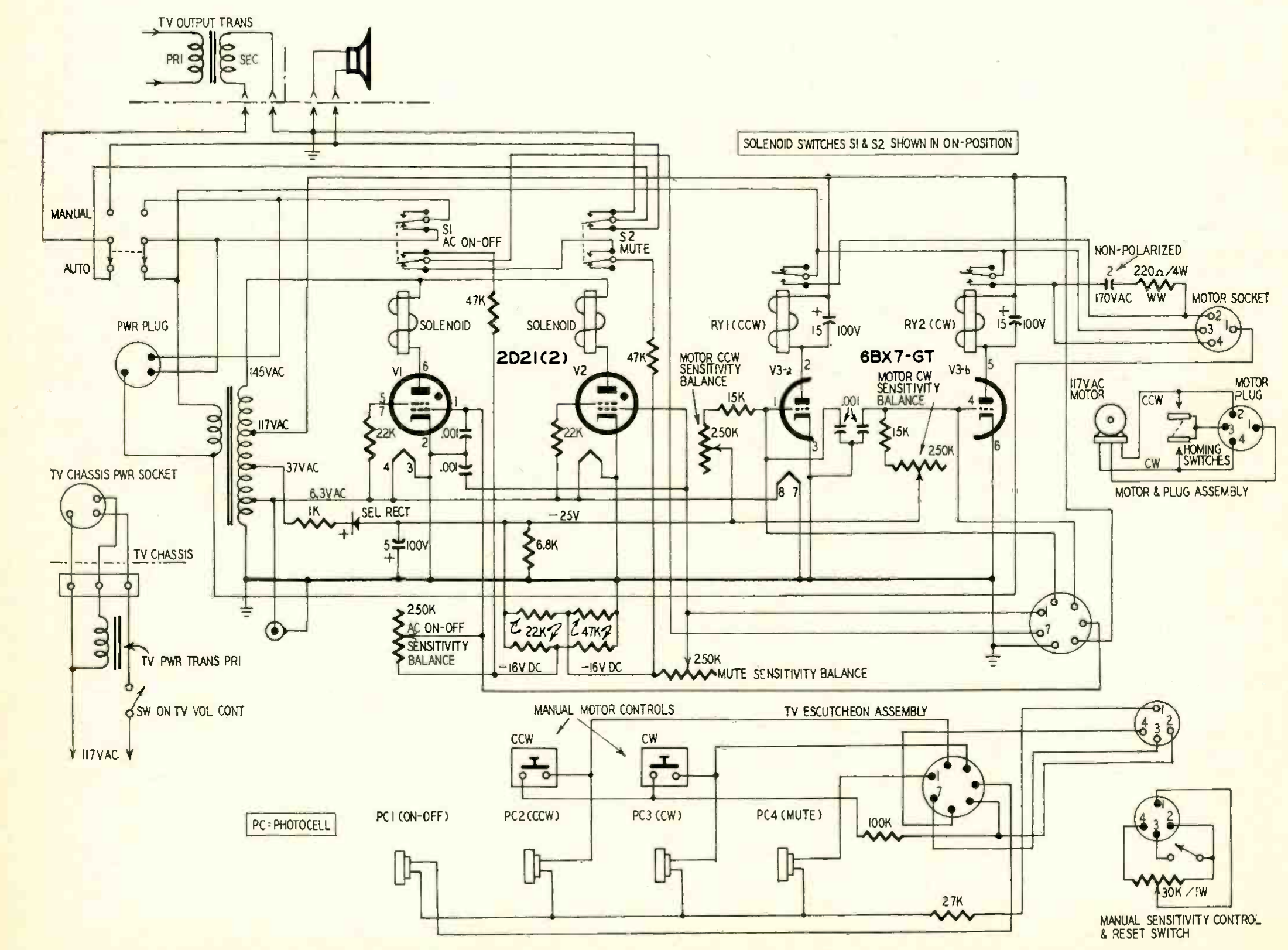
Figure 1 shows the television chassis, the remote-control chassis, and the motor assembly as separate units. In the control chassis, the transformer supplies 6.3 V AC to the heaters and 145 V AC to the 2D21 anode circuits. A tap marked 117 V AC supplies the 6BX7GT relay-drive circuit. The 117 V AC line supply to the motor follows a separate path through the contacts. The 37 V AC tap, a 1 kΩ resistor, and a selenium rectifier feed the negative supply. The positive terminal of the 5 µF capacitor goes to the common reference. A 6.8 kΩ resistor connects the bias node to that reference. The resulting node is marked −25 V DC. [1]
In Auto, with the local power switch closed, the control chassis stays powered after the optical command switches the set off. S1 has disconnected the television transformer primary, so PC1 can still receive a command to turn the set back on. In Manual, selector SW8 in Zenith’s service manual disables remote control and bypasses the mute contact. Operation therefore depends on both S1/S2 and the positions of the local controls. The manual explicitly describes standby with the local power switch set to On. [1] [2]
From CdS resistance to grid voltage
The cadmium sulfide cells act as photoconductive resistors. Openings in the cabinet separate the targets so the viewer can select a branch by aiming the beam. In Figure 1, the wiper of the 30 kΩ master sensitivity control feeds the AC branch shared by the four cells through 27 kΩ. The resistance of each cell determines how much AC reaches its tube. Each grid also has a path to the negative bias supply through an individual balance control. The table follows Maxwell’s designations as seen from the front of the television. [1] [2]
| Input | Position | Tube and actuator | Controlled contact |
|---|---|---|---|
| PC1 | Lower left | V1, 2D21 and solenoid | S1, television transformer primary |
| PC4 | Lower right | V2, 2D21 and solenoid | S2, loudspeaker circuit |
| PC2 | Upper left | V3-a, ½ 6BX7GT and RY1 | Counterclockwise motor drive (CCW) |
| PC3 | Upper right | V3-b, ½ 6BX7GT and RY2 | Clockwise motor drive (CW) |
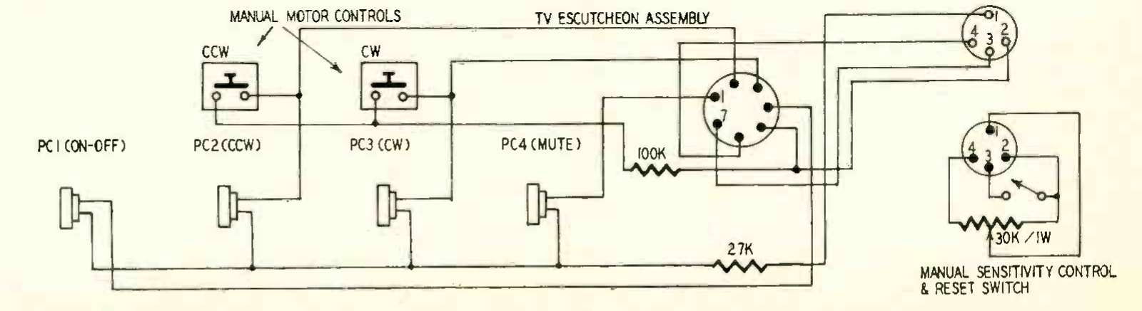
Maxwell gives approximate values of 100 MΩ in darkness and 25 kΩ under strong illumination, a ratio of about 4,000. At high resistance, the bias branch dominates the grid voltage. As cell resistance falls, the AC amplitude increases and the signal source also loads the DC bias divider. Both effects matter when interpreting Figure 2. [1]
The 2D21 thyratrons drive two bistable switches
PC1 and PC4 act on the g1 control grid, pin 1, of V1 and V2. The anode, pin 6, receives 145 V AC through its solenoid coil. The cathode and grid circuit share the reference shown in Figure 2. The grid excitation is synchronous with the anode supply. During a positive half-cycle there is an interval in which the anode can sustain the discharge and the grid signal can reach the firing condition. [1] [5]
Triggering ionizes the gas. The grid then loses control of anode current, whose magnitude is limited by the external circuit. The discharge extinguishes when current drops below the holding current near the end of the conducting half-cycle. The negative half-cycle allows the tube to recover its blocking capability. If the cell remains illuminated, the tube can fire on the next positive half-cycle. The coil therefore sees pulsating unidirectional current at line frequency. [2] [5]
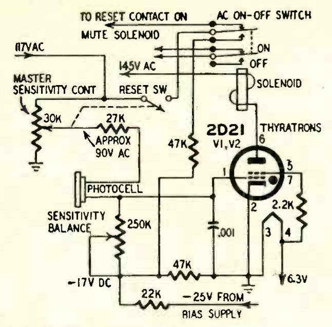
The 145 V AC label identifies the supply to this branch. In a sinusoidal model it corresponds to about 205 V peak at the secondary. During discharge the voltage divides between the tube and the solenoid, with a waveform that also depends on the coil inductance. RCA distinguishes g1 behavior before and during conduction and shows its dependence on anode conditions. The g2 connection also affects firing. Zenith connects g2 pins 5 and 7 to each other and through a resistor to one side of the heater winding. Applying the RCA curves measured with g2 fixed at 0 V would therefore introduce an additional assumption. [1] [2] [5]
The solenoid moves the switch and the contacts retain the state
The patent illustrates how the armature couples to the snap-action switch. One pull-and-release cycle prepares the mechanism for the next actuation, which moves the switch to the opposite position. The 60 Hz current pulses energize the coil. Actual switching occurs on the mechanical timescale of the armature and its latching mechanism. After release, the mechanism retains the contact position. [2] [3]
The power pole of S1 switches the path to the television transformer primary. The audio pole of S2 acts in the output transformer secondary and loudspeaker circuit. In Auto, mute opens the path to the voice coil. Switching therefore takes place on the loudspeaker side. The television power circuit is separate, and the local volume setting stays where it was. [1]
Related article. 2D21 thyratron: a compact model of grid current during anode conduction.
6BX7GT, direction relays, and the two-winding motor
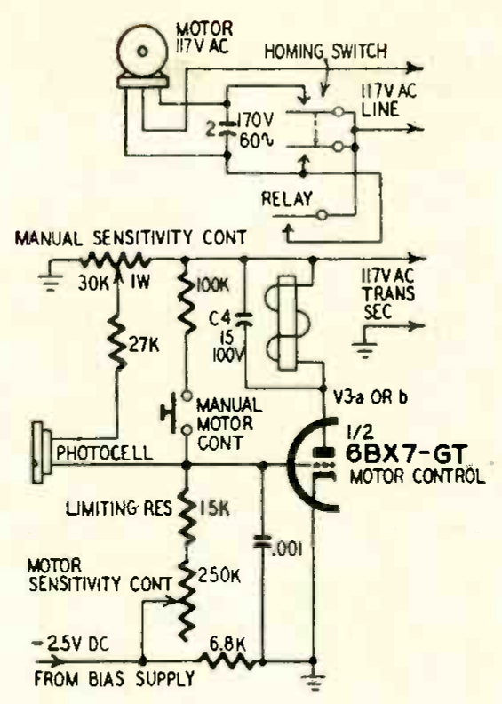
PC2 and PC3 feed the two grids of V3. In the branch shown in Figure 3, the grid returns to −25 V through 15 kΩ and the 250 kΩ balance control. The local push button applies AC to the same grid through a 100 kΩ path independent of the photocell resistance. The manual identifies the push buttons as SW5 and SW6 and also assigns the 15 kΩ resistor the task of limiting cell current. [1] [2]
Each half of the 6BX7GT acts as a control triode with an AC anode supply. When the anode is positive, the grid signal amplitude controls the available current. Zenith specifies about 9 mA average rectified current to operate the relay in the active branch. The relay contacts switch the motor current on the mains side. [2]
Reversing direction with the phase-shift branch
The two induction motor windings share one end. Between the other two ends, the overall schematic shows a branch containing nonpolarized 2 µF C6 and 220 Ω, 4 W R6, using the designations in Zenith’s manual. The relay and cam contacts connect the switched line to one end or the other. One winding is supplied directly and the other through the phase-shift branch. Swapping the winding that receives the phase-shifted current reverses the torque. Figure 3 shows only the capacitor in that branch. The series resistor appears in Figure 1 and in Zenith’s full schematic. [1] [2]
At 60 Hz, the magnitude of the reactance of 2 µF is XC = 1/(2π·60·2 µF) ≈ 1.33 kΩ. The impedance of the series branch alone is about (0.220 − j1.326) kΩ, with a magnitude of 1.34 kΩ. Calculating the actual phase difference between the winding currents requires their impedances as well. The capacitor reactance describes the added branch, while torque depends on the complete electromechanical system.
The cams complete the positioning cycle
The manual identifies the two positioning contacts as SW7A and SW7B. Each is wired in parallel with the command contact for its direction. The cams make one revolution per channel step and open the contact when the turret reaches an indexed position. The relays can thus start the motor from a position where both cam contacts are open. The actual selector position, transmitted by the mechanism, determines when the step is complete. [1] [2]
| Stage | Relay contact | Cam contact | Effect |
|---|---|---|---|
| At an indexed position | Open | Open | Motor stopped |
| Optical start | Closed | Initially open | The motor starts in the selected direction |
| Release between positions | Open after drop-out | Closed | The cam keeps the motor running |
| Next indexed position | Open | Opened by the cam | The motor stops |
| Beam held on | Closed | Opens at every indexed position | The relay path keeps the motor running |
The duration of the light beam governs how many steps the selector passes through. Cam geometry determines where it can stop. If the beam is removed while the motor is running, it stops at the first valid position after relay drop-out. Maxwell’s Figure 4 belongs to the next discussion, about a wired remote selector designed to reach a specific position. For the Flash-Matic, compare Figures 1 and 3 with the description of indexing on p. 36. [1] [3]
Related article. 6BX7-GT: SPICE model, Koren fitting, and validation on General Electric data.
Comparison with Zenith’s service schematic
| Circuit point | Maxwell’s figures | Zenith service manual and interpretation |
|---|---|---|
| Local negative node of the 2D21s | −16 V in both branches in Figure 1, −17 V in the branch in Figure 2. | The service schematic marks −16 V. The unloaded divider gives −17.0 V from a −25 V supply. Both labels refer to the local branch downstream of the −25 V distribution. |
| Resistor to pins 5 and 7 | 22 kΩ in Figure 1, 2.2 kΩ in Figure 2. | The service schematic shows 2.2 kΩ for both tubes. This value applies to g2 and is distinct from the 22 kΩ in the bias dividers. |
| Relay-coil capacitors | 15 µF, 100 V in Maxwell’s drawings. | The service schematic specifies 5 µF, 100 V for C4 and C5. The parts list gives C1, C4, and C5 the same Zenith part number. This difference affects relay hold and release times. |
The manual’s values come from the service schematic reproduced there. The calculations identify the figure and component value used. The original drawings distinguish Maxwell’s published circuit from the values documented for Zenith’s chassis and the estimates derived from the circuit. Zenith, Figure 6 and parts list. [1]
Optical margin, performance, and limitations
The main limitation comes from the detection principle. Steady ambient light can reduce the CdS resistance and pass the AC signal already present in the receiver. The grid then sees a signal with the same frequency and phase relationship as an intended command. Synchronization with the anode helps the 2D21 trigger, but the circuit senses a change in impedance and relies on the beam and the cabinet openings to select the target. Steady light or a reflection can therefore produce an electrically valid command. [1] [2]
The operating manual calls for a sensitivity setting near maximum at 20–25 feet (about 6–7.6 m), depending on the condition of the flashlight batteries, the focus of the beam, and room lighting. The service instructions explicitly mention sunlight, lamps, and reflections from light-colored objects. Moving the threshold closer to the background light level lets a weak beam operate the receiver from farther away, at the cost of more accidental triggering. A false trigger on PC1 or PC4 can latch a new state. Persistent illumination on PC2 or PC3 can keep the selector moving. [2] [6]
The tuner adds a mechanical limitation. Stopping at a valid position requires the cam contacts to open when the turret is centered. An indexing error involves the drive mechanism and position contacts even if the photocell, tube, and relay respond correctly. The manual treats light-level balancing and cam adjustment as separate procedures. [2]
What the Flash-Matic introduced
Zenith’s Lazy Bones already motorized the tuner and let the viewer control it through a cable. The Flash-Matic eliminated that external connection and kept the control logic inside the television. Thyratrons and solenoids provided latching switches. A dual triode and two relays selected direction. The cams provided enough position feedback to complete the step. Detection, actuation, and state retention used components already available, with a handheld flashlight as the source. [2] [6]
With Space Command, which went into production in the fall of 1956, Robert Adler’s group assigned each command to a distinct ultrasonic frequency. In the Flash-Matic, command identity was tied to four physical inputs on the cabinet. Frequency encoding let the receiver distinguish several commands at a single input. In the Flash-Matic, the viewer selected the branch by aiming the light. [6]
References and original issue
- Henry O. Maxwell, Remote Controls for TV, Radio-Electronics, vol. XXVII, no. 9, September 1956, pp. 34–36. The four scans reproduce Figure 1, a detail from it, and Figures 2 and 3. Scan of pp. 34–36.
- Zenith Radio Corporation, Zenith Flash-Matic Remote Control manual. Operating instructions, theory of operation, Figure 6, alignment procedures, and parts list. Figure 6 is on printed p. 10, PDF page 12. Zenith manual, technical section.
- Eugene J. Polley, Control system, US 2,903,575, filed May 6, 1955 and granted September 8, 1959. Patent text and drawings.
- Zenith Radio Corporation, June 13, 1955 press release for the demonstration to journalists and distributors. Scan from the Early Television Museum.
- RCA, 2D21 Thyratron, and General Electric, 6BX7-GT, ET-T804. RCA 2D21 data sheet · GE 6BX7GT data sheet.
- Zenith Electronics, Six Decades of Channel Surfing. Timeline and the transition from Flash-Matic to Space Command. Zenith historical archive.
Download Maxwell’s article · PDF, pp. 34–36
Complete September 1956 issue, 162 pages. World Radio History archive · Google Drive copy (restricted access).
The Flash-Matic in motion
Illustration of the switching sequence. Timings are illustrative.
Reading the two branches. In the power branch, the 2D21 energizes the solenoid and S1 holds its position after the flash. Mute uses the same principle with V2 and S2. During reset, SW9 applies AC to the auxiliary contacts of S1 and S2, then through the 47 kΩ branch to the grid network that needs resetting.
In the motor branch, RY1 starts counterclockwise rotation. Cam contact SW7A, wired in parallel with the RY1 contact, keeps the motor powered when the relay drops out between channels. When the selector reaches the next indexed position, SW7A opens and the motor stops. The figure shows one direction, with illustrative timing. [1] [2]
1 of 7 · At rest. S1, RY1, and SW7A are open.