

OpenFOAM 14 Case 04: Parametric Channel Mesh with the Gmsh Python API
Fourth case of the Learning OpenFOAM 14 path, following Case 03 (Gmsh mesh imported with gmshToFoam). Here the validated channel becomes a parametric generator written in Python: a complete reproducible procedure, parameterized meshing and analytical validation, with OpenFOAM 14.
1. Purpose and learning objective
This exercise converts the previously validated Gmsh channel model into a fully parametric mesh-generation workflow driven by Python.
The objective is not to introduce new CFD physics. The physical model remains the laminar Poiseuille benchmark already validated in Cases 01–03. The new element is automation: channel dimensions and mesh resolution are supplied as command-line parameters, and the Gmsh Python API constructs the geometry and mesh without manual editing of a .geo file.
The complete workflow is:
command-line parameters
        -> Python/Gmsh geometry
        -> structured mesh
        -> gmshToFoam
        -> OpenFOAM
        -> analytical validation
The procedure is designed so that a student can reproduce the complete case from an empty working directory.
2. Prerequisites
Required software:
- OpenFOAM 14
- Gmsh
- Python 3
- Gmsh Python bindings
- ParaView 5.13.2 for optional visualization
Check the tools:
foamVersion
gmsh --version
python3 --version
python3 -c "import gmsh; print(gmsh.__version__)"
command -v gmshToFoam
command -v changeDictionary
command -v checkMesh
command -v foamRun
command -v foamPostProcess
If the Python Gmsh module is missing on Debian:
su -
apt update
apt install python3-gmsh
exit
Verify again:
python3 -c "import gmsh; print(gmsh.__version__)"3. Create the case directory
Create the new case:
cd $FOAM_RUN
mkdir -p 04_parametric_channel/{0,constant,system,geometry}
Reuse the already validated physics from Case 03:
cp 03_gmsh_channel/0/U \
   03_gmsh_channel/0/p \
   04_parametric_channel/0/

cp 03_gmsh_channel/constant/physicalProperties \
   03_gmsh_channel/constant/momentumTransport \
   04_parametric_channel/constant/

cp 03_gmsh_channel/system/controlDict \
   03_gmsh_channel/system/fvSchemes \
   03_gmsh_channel/system/fvSolution \
   03_gmsh_channel/system/graphUniform \
   04_parametric_channel/system/
Enter the case:
cd $FOAM_RUN/04_parametric_channelAt this point there is deliberately no constant/polyMesh: the mesh will be generated by Python/Gmsh.
4. Complete Python mesh generator
Create geometry/generate_channel.py with the following complete content.
#!/usr/bin/env python3

import argparse
import gmsh


def parse_args():
    parser = argparse.ArgumentParser(
        description="Generate a structured parametric channel mesh for OpenFOAM."
    )

    parser.add_argument("--length", type=float, default=0.5)
    parser.add_argument("--gap", type=float, default=0.01)
    parser.add_argument("--depth", type=float, default=0.001)

    parser.add_argument("--nx", type=int, default=200)
    parser.add_argument("--ny", type=int, default=40)
    parser.add_argument("--nz", type=int, default=1)

    parser.add_argument(
        "--output",
        default="geometry/channel.msh"
    )

    return parser.parse_args()


def main():
    args = parse_args()

    if min(args.length, args.gap, args.depth) <= 0:
        raise ValueError("All dimensions must be positive.")

    if min(args.nx, args.ny, args.nz) < 1:
        raise ValueError("Cell counts must be positive integers.")

    L = args.length
    H = args.gap
    D = args.depth

    gmsh.initialize()
    gmsh.model.add("parametric_channel")

    geo = gmsh.model.geo

    # Points
    p1 = geo.addPoint(0.0, -H/2, 0.0)
    p2 = geo.addPoint(L,   -H/2, 0.0)
    p3 = geo.addPoint(L,    H/2, 0.0)
    p4 = geo.addPoint(0.0,  H/2, 0.0)

    p5 = geo.addPoint(0.0, -H/2, D)
    p6 = geo.addPoint(L,   -H/2, D)
    p7 = geo.addPoint(L,    H/2, D)
    p8 = geo.addPoint(0.0,  H/2, D)

    # Lines
    l1 = geo.addLine(p1, p2)
    l2 = geo.addLine(p2, p3)
    l3 = geo.addLine(p3, p4)
    l4 = geo.addLine(p4, p1)

    l5 = geo.addLine(p5, p6)
    l6 = geo.addLine(p6, p7)
    l7 = geo.addLine(p7, p8)
    l8 = geo.addLine(p8, p5)

    l9 = geo.addLine(p1, p5)
    l10 = geo.addLine(p2, p6)
    l11 = geo.addLine(p3, p7)
    l12 = geo.addLine(p4, p8)

    # Surfaces
    s_front = geo.addPlaneSurface([
        geo.addCurveLoop([l1, l2, l3, l4])
    ])

    s_back = geo.addPlaneSurface([
        geo.addCurveLoop([l5, l6, l7, l8])
    ])

    s_bottom = geo.addPlaneSurface([
        geo.addCurveLoop([l1, l10, -l5, -l9])
    ])

    s_outlet = geo.addPlaneSurface([
        geo.addCurveLoop([l2, l11, -l6, -l10])
    ])

    s_top = geo.addPlaneSurface([
        geo.addCurveLoop([l3, l12, -l7, -l11])
    ])

    s_inlet = geo.addPlaneSurface([
        geo.addCurveLoop([l4, l9, -l8, -l12])
    ])

    surface_loop = geo.addSurfaceLoop([
        -s_front,
        s_back,
        s_bottom,
        s_outlet,
        s_top,
        s_inlet
    ])

    volume = geo.addVolume([surface_loop])

    geo.synchronize()

    # Structured mesh.
    # Gmsh expects number of nodes = number of cells + 1.
    for curve in [l1, l3, l5, l7]:
        gmsh.model.mesh.setTransfiniteCurve(curve, args.nx + 1)

    for curve in [l2, l4, l6, l8]:
        gmsh.model.mesh.setTransfiniteCurve(curve, args.ny + 1)

    for curve in [l9, l10, l11, l12]:
        gmsh.model.mesh.setTransfiniteCurve(curve, args.nz + 1)

    surfaces = {
        s_front:  [p1, p2, p3, p4],
        s_back:   [p5, p6, p7, p8],
        s_bottom: [p1, p2, p6, p5],
        s_outlet: [p2, p3, p7, p6],
        s_top:    [p4, p3, p7, p8],
        s_inlet:  [p1, p4, p8, p5],
    }

    for surface, corners in surfaces.items():
        gmsh.model.mesh.setTransfiniteSurface(
            surface,
            cornerTags=corners
        )
        gmsh.model.mesh.setRecombine(2, surface)

    gmsh.model.mesh.setTransfiniteVolume(
        volume,
        cornerTags=[p1, p2, p3, p4, p5, p6, p7, p8]
    )

    # Physical groups become OpenFOAM patch names.
    gmsh.model.addPhysicalGroup(
        2, [s_front, s_back],
        name="frontAndBack"
    )

    gmsh.model.addPhysicalGroup(
        2, [s_bottom, s_top],
        name="walls"
    )

    gmsh.model.addPhysicalGroup(
        2, [s_outlet],
        name="outlet"
    )

    gmsh.model.addPhysicalGroup(
        2, [s_inlet],
        name="inlet"
    )

    gmsh.model.addPhysicalGroup(
        3, [volume],
        name="fluid"
    )

    # gmshToFoam-friendly mesh format.
    gmsh.option.setNumber("Mesh.MshFileVersion", 2.2)
    gmsh.option.setNumber("Mesh.Binary", 0)

    gmsh.model.mesh.generate(3)
    gmsh.write(args.output)

    print()
    print("PARAMETRIC CHANNEL GENERATED")
    print(f"Length : {L:.6g} m")
    print(f"Gap    : {H:.6g} m")
    print(f"Depth  : {D:.6g} m")
    print(f"Cells  : {args.nx} x {args.ny} x {args.nz}")
    print(f"Total  : {args.nx * args.ny * args.nz}")
    print(f"Output : {args.output}")

    gmsh.finalize()


if __name__ == "__main__":
    main()
Make the script executable:
chmod +x geometry/generate_channel.py5. Reference generation test
The first test must reproduce the already validated 8000-cell channel from Case 03.
Run:
python3 geometry/generate_channel.py \
    --length 0.5 \
    --gap 0.01 \
    --depth 0.001 \
    --nx 200 \
    --ny 40 \
    --nz 1 \
    --output geometry/channel.msh
Expected terminal summary:
PARAMETRIC CHANNEL GENERATED
Length : 0.5 m
Gap    : 0.01 m
Depth  : 0.001 m
Cells  : 200 x 40 x 1
Total  : 8000
Output : geometry/channel.msh
6. Import the reference mesh into OpenFOAM
Import the mesh:
gmshToFoam geometry/channel.msh | tee log.gmshToFoamCreate system/changeDictionaryDict:
FoamFile
{
    format          ascii;
    class           dictionary;
    object          changeDictionaryDict;
}

boundary
{
    walls
    {
        type wall;
    }

    frontAndBack
    {
        type empty;
    }
}
Apply the patch-type corrections:
changeDictionaryCheck the mesh:
checkMesh | tee log.checkMeshExtract the important information:
grep -E 'points:|faces:|cells:|hexahedra:|Mesh OK' log.checkMeshExpected result:
points:               16482
faces:                32240
cells:                8000
hexahedra:            8000
Mesh OK.
Check the boundary types:
grep -A6 -E 'inlet|outlet|walls|frontAndBack' \
    constant/polyMesh/boundary
Expected operational types:
frontAndBack→emptywalls→walloutlet→patchinlet→patch
This first test demonstrates that the Python script reproduces the validated Case 03 mesh.
7. Demonstrate real parametrization
The second test changes both geometry and mesh resolution without editing the Python source.
Target parameters:
| Parameter | Reference | Parametric test |
|---|---|---|
| Length | 0.50 m | 0.75 m |
| Gap | 0.010 m | 0.015 m |
| Depth | 0.001 m | 0.001 m |
| Nx | 200 | 300 |
| Ny | 40 | 60 |
| Nz | 1 | 1 |
| Total cells | 8000 | 18000 |
Preserve the reference files if desired:
mv geometry/channel.msh geometry/channel_reference.msh
mv constant/polyMesh constant/polyMesh_reference
Generate the new geometry:
python3 geometry/generate_channel.py \
    --length 0.75 \
    --gap 0.015 \
    --depth 0.001 \
    --nx 300 \
    --ny 60 \
    --nz 1 \
    --output geometry/channel.msh
Expected summary:
PARAMETRIC CHANNEL GENERATED
Length : 0.75 m
Gap    : 0.015 m
Depth  : 0.001 m
Cells  : 300 x 60 x 1
Total  : 18000
Output : geometry/channel.msh
Import and verify:
gmshToFoam geometry/channel.msh | tee log.gmshToFoam_parametric
changeDictionary
checkMesh | tee log.checkMesh_parametric
Extract the relevant mesh information:
grep -E 'points:|faces:|cells:|hexahedra:|Mesh OK' \
    log.checkMesh_parametric
Measured result:
points:           36722
faces:            72360
cells:            18000
hexahedra:        18000
Mesh OK.
The second geometry therefore demonstrates true command-line parametrization: the source code is unchanged while the resulting geometry and mesh are different.
8. Physical interpretation of the second case
The inlet velocity remains
Umean = 0.01 m/s
but the new gap is
H = 0.015 m.
The hydraulic diameter is
Dh = 2H = 0.03 m
and therefore
Re = Umean Dh / ν = (0.01 · 0.03) / 10−6 = 300.
The flow is still laminar.
The theoretical fully developed maximum velocity remains
Umax,theory = 1.5 Umean = 0.015 m/s.
The theoretical kinematic pressure gradient becomes
dp/dx = −12 ν Umean / H2 = −5.3333 × 10⁻⁴ m/s2.
9. Update the sampling line
Because the gap changed, the post-processing line must also be adapted to the new geometry.
Replace system/graphUniform with:
FoamFile
{
    format      ascii;
    class       dictionary;
    object      graphUniform;
}

start           (0.675 -0.007375 0.0005);
end             (0.675  0.007375 0.0005);

nPoints         201;

fields          (U);

axis            y;

#includeEtc "caseDicts/postProcessing/graphs/graphUniform.cfg"
The line is placed at x = 0.675 m, close to the outlet but inside the fluid domain. Using 201 points ensures that y = 0 is sampled exactly.
10. Run the parametric CFD case
Run the steady solver:
foamRun | tee log.foamRun_parametricThen perform the line sampling:
foamPostProcess \
    -solver incompressibleFluid \
    -func graphUniform \
    -latestTime
Locate the generated file:
find postProcessing/graphUniform -name line.xy11. Analytical validation script
Use the following complete command to compare the sampled profile against the Poiseuille solution for the new 15 mm gap.
f=$(find postProcessing/graphUniform \
    -name line.xy | sort -V | tail -1)

awk '
BEGIN {
    H=0.015
    Umean=0.01
    UmaxTheory=1.5*Umean
    umax=-1
}

$1 !~ /^#/ && NF >= 2 {
    y=$1
    u=$2

    uth=UmaxTheory*(1-(2*y/H)^2)

    e=u-uth
    ae=(e<0 ? -e : e)

    sumsq += e*e
    n++

    if (ae > maxerr) {
        maxerr=ae
        maxerr_y=y
    }

    if (u > umax) {
        umax=u
        umax_y=y
    }
}

END {
    rmse=sqrt(sumsq/n)

    printf "Points                 : %d\n",n
    printf "CFD maximum Ux         : %.10f m/s\n",umax
    printf "Location of max        : %.7f m\n",umax_y
    printf "Theoretical Umax       : %.10f m/s\n",UmaxTheory
    printf "RMSE                   : %.10e m/s\n",rmse
    printf "Normalized RMSE        : %.6f %%\n",100*rmse/UmaxTheory
    printf "Maximum abs error      : %.10e m/s\n",maxerr
    printf "Max error / Umax       : %.6f %%\n",100*maxerr/UmaxTheory
    printf "Max-error y            : %.7f m\n",maxerr_y
}' "$f"
12. Measured validation result
The 18000-cell parametric case produced:
Points              : 201
CFD maximum Ux      : 0.0149916640 m/s
Location of max     : -0.0000000 m
Theoretical Umax    : 0.0150000000 m/s
RMSE                : 8.8275000912e-06 m/s
Normalized RMSE     : 0.058850 %
Maximum abs error   : 1.2469583333e-05 m/s
Max error / Umax    : 0.083131 %
Max-error y         : -0.0003687 m
The numerical solution therefore reproduces the analytical profile to substantially better than 0.1% using the normalized RMSE and maximum-error metrics.
The maximum velocity occurs at the channel centerline, as required by the analytical solution.
13. ParaView visualization
Create a permanent ParaView marker file:
touch parametric_channel.foamUsing the ParaView client connected to pvserver, open:
/home/<user>/OpenFOAM/<user>-14/run/04_parametric_channel/parametric_channel.foamSelect the final time and display:
U -> Magnitude
Representation -> Surface
The expected visualization is a symmetric parabolic velocity distribution with maximum velocity at the center of the enlarged channel.
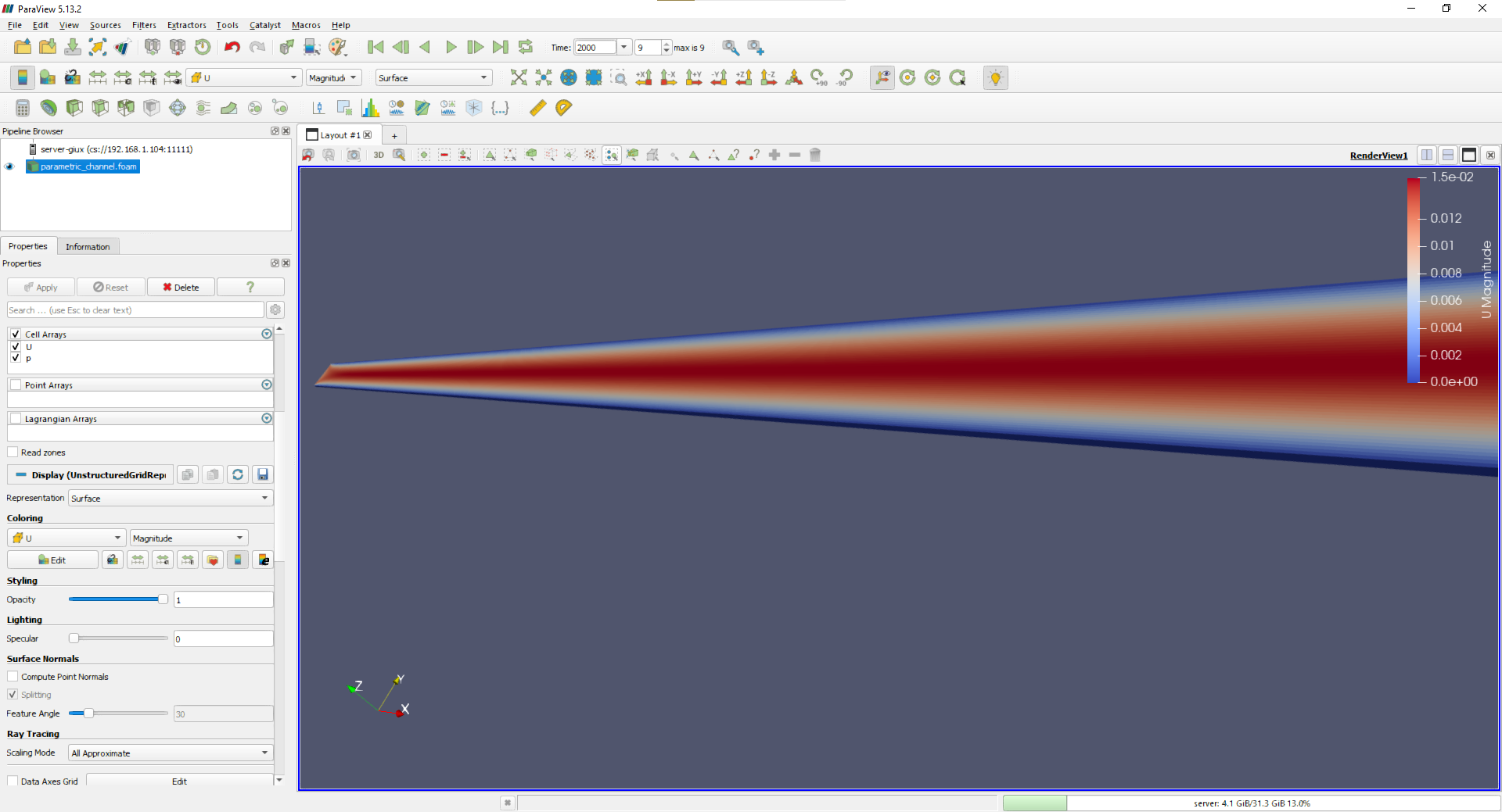
The screenshot is sufficient for this exercise because streamline construction, wireframe visualization and basic ParaView interaction were already covered in earlier training cases. The learning objective here is parameterized geometry generation and reproducibility.
14. What has been demonstrated
Case 04 establishes the following workflow:
- a single Python source file defines the geometric construction logic;
- dimensions and mesh density are provided externally as parameters;
- Gmsh generates a structured hexahedral mesh;
- physical groups are converted into OpenFOAM patch names;
changeDictionaryassigns the required OpenFOAM patch types;checkMeshverifies the generated grid;- OpenFOAM solves the same physical problem on the new geometry;
- the result is validated quantitatively against an analytical solution.
The same script generated both:
0.50 m x 0.010 m -> 200 x 40 x 1 -> 8000 cells
0.75 m x 0.015 m -> 300 x 60 x 1 -> 18000 cells
without editing the Python source.
15. Acceptance criteria
The exercise is complete when all of the following are true:
import gmshsucceeds in Python;- the reference command generates 8000 cells;
- the second command generates 18000 cells;
- both meshes contain only hexahedra;
- both meshes pass
checkMesh; - the OpenFOAM patch types are correct;
- the parametric CFD case converges normally;
- the 18000-cell velocity profile has normalized RMSE below 0.1%;
- the maximum velocity is located on the centerline;
- the ParaView result shows the expected symmetric velocity distribution.
16. Final conclusion
This exercise converts mesh generation from a manually edited geometry file into a reproducible parametric process. A student can now create families of related CFD geometries by modifying only command-line values for dimensions and mesh resolution.
This pattern is directly extensible to more complex geometries: the geometry-generation logic remains in a version-controlled Python script, while experimental or design variations are represented by explicit parameters rather than manual CAD edits.
The parametric channel is the starting point of Case 05, on parallel runs with MPI. The previous case is Case 03.