

OpenFOAM 14 Case 03: Importing a Gmsh Mesh with gmshToFoam
Third case of the Learning OpenFOAM 14 path: complete reproducible procedure, mesh import and analytical validation. I rebuild the laminar channel from Case 01 (also used in the Case 02 mesh convergence study) with an external Gmsh mesh instead of blockMesh.
1. Purpose
This handout reproduces the laminar channel benchmark using an external Gmsh mesh instead of blockMesh. The physical model, boundary conditions, solver settings and analytical reference are intentionally kept identical to CFD Training Case 01. The only controlled change is the mesh-generation route.
The workflow is:
Gmsh geometry → Gmsh mesh → gmshToFoam → OpenFOAM → analytical validation.
The exercise demonstrates how to separate geometry/meshing from the CFD solver while preserving a verifiable benchmark.
2. Target result
| Quantity | Result |
|---|---|
| Mesh generator | Gmsh |
| Import utility | gmshToFoam |
| Mesh format | MSH 2.2 ASCII |
| Cells | 8000 |
| Cell type | 8000 hexahedra |
| checkMesh | Mesh OK |
| CFD sampled maximum Ux | 0.0149625470 m/s |
| Theoretical maximum Ux | 0.0150000000 m/s |
| Normalized RMSE | 0.150343 % |
| Comparison with Case 01 | numerically indistinguishable |
3. Prerequisites
Check the required tools:
gmsh --version
command -v gmshToFoam
command -v changeDictionary
command -v checkMesh
command -v foamRun
If Gmsh is not installed on Debian:
su -
apt update
apt install gmsh
exit
The OpenFOAM 14 environment must already be loaded.
4. Create the case directory
The new case reuses the validated physics from Case 01 so that only the mesh-generation method changes.
cd $FOAM_RUN
mkdir -p 03_gmsh_channel/{0,constant,system,geometry}
Copy the validated physical and numerical dictionaries from Case 01:
cp 01_laminar_channel/0/U \
   01_laminar_channel/0/p \
   03_gmsh_channel/0/

cp 01_laminar_channel/constant/physicalProperties \
   01_laminar_channel/constant/momentumTransport \
   03_gmsh_channel/constant/

cp 01_laminar_channel/system/controlDict \
   01_laminar_channel/system/fvSchemes \
   01_laminar_channel/system/fvSolution \
   03_gmsh_channel/system/

cd $FOAM_RUN/03_gmsh_channel
No blockMeshDict is used in this case.
5. Gmsh geometry and structured mesh
Create geometry/channel.geo with the following complete content:
// Laminar channel benchmark
// Geometry: 0.5 x 0.01 x 0.001 m
// Structured mesh: 200 x 40 x 1 cells

Mesh.MshFileVersion = 2.2;
Mesh.Binary = 0;

// Points
Point(1) = {0.0, -0.005, 0.0};
Point(2) = {0.5, -0.005, 0.0};
Point(3) = {0.5,  0.005, 0.0};
Point(4) = {0.0,  0.005, 0.0};

Point(5) = {0.0, -0.005, 0.001};
Point(6) = {0.5, -0.005, 0.001};
Point(7) = {0.5,  0.005, 0.001};
Point(8) = {0.0,  0.005, 0.001};

// Edges
Line(1) = {1,2};
Line(2) = {2,3};
Line(3) = {3,4};
Line(4) = {4,1};

Line(5) = {5,6};
Line(6) = {6,7};
Line(7) = {7,8};
Line(8) = {8,5};

Line(9)  = {1,5};
Line(10) = {2,6};
Line(11) = {3,7};
Line(12) = {4,8};

// Surfaces
Curve Loop(1) = {1,2,3,4};
Plane Surface(1) = {1};

Curve Loop(2) = {5,6,7,8};
Plane Surface(2) = {2};

Curve Loop(3) = {1,10,-5,-9};
Plane Surface(3) = {3};

Curve Loop(4) = {2,11,-6,-10};
Plane Surface(4) = {4};

Curve Loop(5) = {3,12,-7,-11};
Plane Surface(5) = {5};

Curve Loop(6) = {4,9,-8,-12};
Plane Surface(6) = {6};

// Volume
Surface Loop(1) = {-1,2,3,4,5,6};
Volume(1) = {1};

// Structured resolution
Transfinite Curve {1,3,5,7} = 201;
Transfinite Curve {2,4,6,8} = 41;
Transfinite Curve {9,10,11,12} = 2;

Transfinite Surface {1,2,3,4,5,6};
Recombine Surface {1,2,3,4,5,6};
Transfinite Volume {1} = {1,2,3,4,5,6,7,8};

// OpenFOAM boundary names
Physical Surface("frontAndBack") = {1,2};
Physical Surface("walls")        = {3,5};
Physical Surface("outlet")       = {4};
Physical Surface("inlet")        = {6};

Physical Volume("fluid") = {1};
The Transfinite definitions specify node counts. Therefore:
- 201 nodes in x → 200 cells
- 41 nodes in y → 40 cells
- 2 nodes in z → 1 cell
Total:
200 × 40 × 1 = 8000 cells.
6. Generate the Gmsh mesh
Run:
gmsh -3 geometry/channel.geo \
     -format msh2 \
     -o geometry/channel.msh
Check that the file exists:
ls -lh geometry/channel.mshThe msh2 format is used deliberately because it is straightforward for gmshToFoam and preserves the physical names required for patch mapping.
7. Import the mesh into OpenFOAM
Run:
gmshToFoam geometry/channel.msh | tee log.gmshToFoamThe validated import reported:
Vertices to be read: 16482
Cells to be read: 24480

Cells:
    total:8000
    hex :8000
    prism:0
    pyr :0
    tet :0

Patch 0 gets name frontAndBack
Patch 1 gets name walls
Patch 2 gets name outlet
Patch 3 gets name inlet

Writing zone 0 to cellZone fluid and cellSet
End
The Gmsh Physical Surface names are therefore transferred to OpenFOAM patch names.
8. Correct the OpenFOAM patch types
After gmshToFoam, imported surface groups are normally generic patches. The solver requires:
walls→wallfrontAndBack→empty
Create system/changeDictionaryDict:
FoamFile
{
    format      ascii;
    class       dictionary;
    object      changeDictionaryDict;
}

boundary
{
    walls
    {
        type wall;
    }

    frontAndBack
    {
        type empty;
    }
}
Apply the changes:
changeDictionary9. Verify the imported mesh
Run:
checkMesh | tee log.checkMeshExtract the key values:
grep -E \
"points:|faces:|cells:|hexahedra:|max aspect ratio|Mesh OK" \
log.checkMesh
Validated result:
points:               16482
faces:                32240
cells:                8000
hexahedra:            8000
Mesh OK.
Verify the boundary file:
grep -A6 -E \
"inlet|outlet|walls|frontAndBack" \
constant/polyMesh/boundary
Expected operational patch types:
frontAndBack   type empty
walls          type wall
outlet         type patch
inlet          type patch
10. Physical and numerical files
The following files are intentionally identical to Case 01:
0/U0/pconstant/physicalPropertiesconstant/momentumTransportsystem/controlDictsystem/fvSchemessystem/fvSolution
This is essential for the comparison: the mesh generator is the only intended change.
Key physical values remain:
Uinlet = (0.01 0 0) m/s
nu     = 1e-6 m^2/s
simulationType = laminar
The steady run uses solver incompressibleFluid; and endTime 2000; exactly as in Case 01.
11. Execute the CFD calculation
Run:
foamRun | tee log.foamRunInspect the end of the log:
tail -40 log.foamRunThe calculation should terminate normally with:
End12. Recreate the velocity-profile sampling
Create system/graphUniform:
FoamFile
{
    format      ascii;
    class       dictionary;
    object      graphUniform;
}

start       (0.45 -0.004875 0.0005);
end         (0.45  0.004875 0.0005);
nPoints     40;

fields      (U);

axis        y;

#includeEtc "caseDicts/postProcessing/graphs/graphUniform.cfg"
Run:
foamPostProcess \
    -solver incompressibleFluid \
    -func graphUniform \
    -latestTime
Locate the output:
find postProcessing/graphUniform -name line.xyExpected file:
postProcessing/graphUniform/2000/line.xy13. Quantitative analytical validation
Run the same comparison used for the blockMesh benchmark:
f=$(find postProcessing/graphUniform -name line.xy | sort -V | tail -1)

awk '
BEGIN {
    H=0.01
    Umean=0.01
    UmaxTheory=1.5*Umean
    umax=-1
}
$1 !~ /^#/ && NF >= 2 {
    y=$1
    u=$2

    uth=UmaxTheory*(1-(2*y/H)^2)

    e=u-uth
    ae=(e<0 ? -e : e)

    sumsq += e*e
    n++

    if (ae > maxerr)
        maxerr=ae

    if (u > umax)
        umax=u
}
END {
    rmse=sqrt(sumsq/n)

    printf "Points                 : %d\n",n
    printf "CFD maximum Ux         : %.10f m/s\n",umax
    printf "Theoretical Umax       : %.10f m/s\n",UmaxTheory
    printf "RMSE                   : %.10e m/s\n",rmse
    printf "Normalized RMSE        : %.6f %%\n",100*rmse/UmaxTheory
    printf "Maximum abs error      : %.10e m/s\n",maxerr
    printf "Max error / Umax       : %.6f %%\n",100*maxerr/UmaxTheory
}' "$f"
Validated Gmsh result:
Points              : 40
CFD maximum Ux      : 0.0149625470 m/s
Theoretical Umax    : 0.0150000000 m/s
RMSE                : 2.2551524240e-05 m/s
Normalized RMSE     : 0.150343 %
Maximum abs error   : 2.8078000000e-05 m/s
Max error / Umax    : 0.187187 %
14. Direct comparison with the blockMesh benchmark
| Meshing route | Cells | Umax [m/s] | NRMSE [%] |
|---|---|---|---|
blockMesh – Case 01 | 8000 | 0.0149625470 | 0.150343 |
Gmsh -> gmshToFoam – Case 03 | 8000 | 0.0149625470 | 0.150343 |
The RMSE values differ by only approximately
5.31 × 10⁻¹² m/s,
which is negligible for this benchmark. The two CFD solutions are numerically indistinguishable.
This confirms that the solution is not tied to blockMesh; an equivalent structured mesh imported from Gmsh produces the same physical result.
15. ParaView visualization
Create a marker file:
cd $FOAM_RUN/03_gmsh_channel
touch gmsh_channel.foam
If pvserver is already running and the client is connected, no reconnection is necessary. In ParaView:
File -> Openand open:
$FOAM_RUN/03_gmsh_channel/gmsh_channel.foamSelect internalMesh, enable U and p, then press Apply.
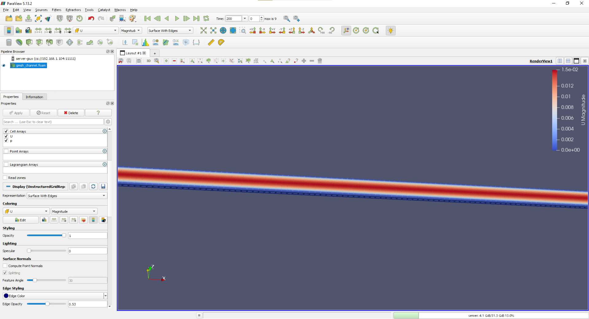
Recommended display:
Representation = Surface With Edges
Coloring       = U -> Magnitude
The image below shows the validated velocity field on the imported Gmsh mesh.
16. Streamline check
The same Stream Tracer settings as Case 01 can be used:
| Property | Value |
|---|---|
| Vectors | U |
| Integration Direction | FORWARD |
| Seed Type | Line |
| Point1 | (0.001, -0.0045, 0.0005) |
| Point2 | (0.001, +0.0045, 0.0005) |
| Resolution | 20 |
| Maximum Streamline Length | 0.5 m |
The streamlines should remain straight and parallel to the channel axis, as in the blockMesh solution.
17. Generic troubleshooting
| Symptom | Check / correction |
|---|---|
| Gmsh physical names do not appear as OpenFOAM patches | ensure the surfaces are declared as Physical Surface groups |
| import behavior is inconsistent | generate an ASCII MSH 2.2 file with -format msh2 |
walls remains a generic patch | run changeDictionary using the supplied dictionary |
frontAndBack remains a generic patch | set its type to empty before the CFD run |
checkMesh cell count is not 8000 | verify the transfinite node counts: 201, 41 and 2 |
| ParaView does not show the case file | create it with touch gmsh_channel.foam |
| no post-processing file appears | use foamPostProcess -solver incompressibleFluid -func graphUniform -latestTime |
18. Acceptance criteria
| Acceptance criterion | Status |
|---|---|
| Gmsh generates the structured volume mesh | PASS |
gmshToFoam imports all named patches | PASS |
| imported mesh contains 8000 hexahedra | PASS |
checkMesh reports Mesh OK | PASS |
walls is wall and frontAndBack is empty | PASS |
| OpenFOAM run converges normally | PASS |
| velocity profile agrees with Poiseuille theory | PASS |
| NRMSE = 0.150343% | PASS |
| Gmsh result matches the blockMesh benchmark | PASS |
| ParaView visualization is correct | PASS |
Final status: CASE 03 COMPLETE AND VALIDATED.
19. Reproducibility checklist
- Verify Gmsh and OpenFOAM utilities.
- Create
03_gmsh_channel. - Copy the validated physical/numerical files from Case 01.
- Create the complete
geometry/channel.geofile. - Generate
geometry/channel.mshin MSH 2.2 format. - Import with
gmshToFoam. - Create
changeDictionaryDictand runchangeDictionary. - Run
checkMeshand verify 8000 hexahedra plusMesh OK. - Run
foamRun. - Create
graphUniformand sample the final velocity profile. - Compare the sampled profile with the analytical Poiseuille solution.
- Create
gmsh_channel.foam. - Open the case through the existing ParaView client-server connection.
- Verify U, p, mesh edges and streamlines.
The case demonstrates a complete external-meshing workflow while retaining the same validated CFD physics as the baseline case.
Previous case: Case 02 – mesh convergence study. Next case: Case 04 – parametric mesh with Gmsh and Python, where the same geometry is generated by a parametric Python script.