

OpenFOAM 14 Part 8: Reading and Creating Cases Independently
Part 8 of 8 – the last unit – of the case-construction series in Learning OpenFOAM 14. The seven previous parts each took one group of files apart: the dictionary language, the mesh, fields and boundary conditions, run control, schemes, linear solvers and algorithms, and finally physical properties and models in Part 7.
This part puts the whole set back together and changes the point of view. It no longer explains a single dictionary: it teaches how to find reliable information in the official OpenFOAM Foundation v14 documentation and in the installed tools, how to turn that information into a minimal working configuration, how to diagnose what goes wrong, and how to build a complete case from an empty directory – the capstone project – explaining every file in it.
Prerequisites. Final unit after Parts 1–7. Platform: OpenFOAM Foundation 14 (openfoam.org / CFD Direct), Bash shell with the environment sourced. The motto of the unit, from its cover: understand → find → configure → verify → explain.
The final learning contract
This is the concluding unit of the OpenFOAM 14 case-construction course. It is not a catalogue of every available keyword. The objective is to locate reliable information, transform it into a minimal working configuration, and explain what was done.
You should be able to do these five things
- Identify the physical requirement and the responsible OpenFOAM component.
- Locate the correct v14 dictionary, field, model or utility.
- Discover documented syntax and examples rather than guessing.
- Apply a small, controlled change and diagnose any failure.
- Assemble, run and document a new simple CFD case.

Working rule
Find evidence before making a change. A valid keyword in another solver, another physical model, or another OpenFOAM distribution is not necessarily appropriate to this case.
Optional background: documentation as an engineering skill
Configuration errors are not merely typing mistakes. A plausible file can encode the wrong physical model. The purpose of documentation literacy is to make each assumption explicit and testable.
Deep dive: the five-step loop, step by step, with the tool that proves each step
The workflow in the figure is a loop, not a line: the “Explain” step of one change produces the next question. What makes it engineering rather than trial and error is that every step leaves a verifiable trace. The table maps each step onto the OpenFOAM v14 tool that produces that trace and onto the part of this series where the tool was introduced.
| Step | Question it answers | Typical v14 evidence | Where in the series |
|---|---|---|---|
| Question | Which physical or numerical behaviour must change? | A one-line hypothesis naming the file and entry | Section 01 below |
| Documentation | Which object implements it and what does it require? | User Guide section, foamInfo, foamToC, a tutorial path | Sections 02, 03, 06–08 |
| Minimal change | What is the smallest edit that expresses it? | A saved copy plus foamDictionary -set and diff -u | Section 05; Part 1 |
| Check | Is it syntactically admissible, and does it run? | foamDictionary -value, checkMesh, the solver log | Sections 12–15 |
| Explain | Why is this change correct for this physics? | A written record: file → entry → role → source | Exercises 16–18, capstone |
Two consequences follow. First, a change that cannot be traced back to a source is not finished, even if the run succeeds. Second, a failure is not wasted time: if each step was recorded, the step at which the chain broke is visible, and the diagnosis starts from there rather than from the beginning.
01 Start from the CFD requirement
An unfamiliar task is not solved by opening random files. Classify the request first: is it about geometry, fields, physical properties, numerical schemes, linear solution, run control or post-processing?
| Question asked | Investigate first |
|---|---|
| Change channel height | system/blockMeshDict; regenerate and check mesh |
| Change inlet speed | 0/U and the corresponding mesh patch |
| Change kinematic viscosity | constant/physicalProperties |
| Change gradient/discretisation | system/fvSchemes |
| Change pressure solver tolerance | system/fvSolution |
| Change output frequency | system/controlDict |
| Add an integrated measurement | function objects; guide Chapter 7 |
Before editing, write a one-line hypothesis
Example: “To prescribe velocity at the inlet, I need the inlet patch in 0/U, not a change to the mesh boundary type.” Verify that the patch already exists in the mesh.
A useful distinction
A mesh patch describes geometry/topology; a field boundary condition describes how a physical variable behaves on that patch.
Deep dive: the routing table, extended to the requests the table does not list
The seven rows above cover the capstone. In practice the same classification extends to other frequent requests. The rows below fill the most common gaps; each one names the v14 file and the User Guide chapter where the syntax is documented.
| Question asked | Investigate first | Guide / series |
|---|---|---|
| Change the time step or the end time | system/controlDict (deltaT, endTime; for transient runs adjustTimeStep, maxCo) | 4.4; Part 4 |
| Switch from laminar to a turbulence model | constant/momentumTransport, then the new fields (k, epsilon or omega, nut) in 0/ | 8.2; Part 7 |
| Non-uniform initial field | 0/<field> internalField, field functions and field sources | 6.1–6.2 |
| Add a source term or a constraint | constant/fvModels, system/fvConstraints | foamToC -fvModels, -fvConstraints |
| Run in parallel | system/decomposeParDict | 3.4; worked case 5 |
| Refine the mesh | system/blockMeshDict cell counts and grading | 5.4; Part 2, worked case 2 |
| Change the linear-solver smoother or the relaxation | system/fvSolution | 4.6; Part 6 |
The hypothesis line has a precise form: “to obtain X, I change entry Y in file Z, and I expect W.” If you cannot fill in Y and Z, the classification step is not finished; if you cannot fill in W, you will not be able to tell whether the change worked.
Deep dive: patch type, boundary condition and initial field are three different layers
The useful distinction above is the root of many errors, so it is worth making it concrete. The mesh layer lives in constant/polyMesh/boundary, generated by blockMesh from the boundary list of blockMeshDict (Part 2). Each patch has a name, a geometric type (patch, wall, empty, symmetryPlane, wedge, cyclic…), a number of faces and a start face. The field layer lives in 0/U, 0/p, and so on (Part 3): for each patch name, a boundary condition tells the solver how that variable behaves there. The initial-field layer is the internalField of the same files: the starting value in the cells, which in a steady run is only an initial guess.
// constant/polyMesh/boundary (generated by blockMesh, excerpt)
frontAndBack
{
    type            empty;
    nFaces          2560;
    startFace       2656;
}

// 0/U (written by you)
frontAndBack { type empty; }
Two rules connect the layers. (1) Every patch name in the mesh must appear in the boundaryField of every field that the solver reads (a regular-expression key such as "(walls|frontAndBack)" also counts). (2) Constraint types (empty, wedge, symmetryPlane, cyclic, processor) are geometric statements, and the field must repeat the same constraint type on that patch: an empty mesh patch with a fixedValue velocity is rejected when the field is read. Generic patch and wall patches, instead, accept any compatible physical condition – that is where the modelling choice happens. With many patches it is easy to miss one; check it mechanically:
# Patch names known to the mesh (checkMesh prints them with face counts)
checkMesh | sed -n '/Patch/,/^$/p'
# Patch names known to each field file
foamDictionary -entry boundaryField -keywords 0/U
foamDictionary -entry boundaryField -keywords 0/p
02 Navigate the official v14 User Guide
The documentation is structured. Use its table of contents before searching with generic terms. The numbers below refer to the OpenFOAM Foundation / CFD Direct version 14 User Guide.
| Guide location | What to use it for |
|---|---|
| Chapter 2 | Worked cases and examples |
| 4.1–4.2 | Case directories, dictionaries, field format, includes |
| 4.4 | controlDict and time/output controls |
| 4.5 | fvSchemes; operators and discretisation |
| 4.6 | fvSolution; solvers and coupling algorithms |
| 4.7 | foamDictionary, foamSearch, foamGet, foamInfo, foamToC, foamFind |
| Chapter 5 | Mesh generation, patch types and blockMesh |
| Chapter 6 | Fields and boundary conditions |
| Chapter 7 | Function objects and post-processing |
| Chapter 8 | Physical-property and transport models |
Primary reference
https://doc.cfd.direct/openfoam/user-guide-v14/
Always check the version selector on the page. Examples on the internet are often written for different OpenFOAM releases.
Deep dive: direct links to the v14 sections you will use most
The official v14 guide has 8 chapters and 39 numbered sections. The table lists the pages that correspond to the topics of this series, with their exact titles (Chapter 6 is officially called “Field and boundary initialisation”: besides boundary conditions it covers field functions and field sources).
| Section | Official title | Series part |
|---|---|---|
| 2.1 | Backward-facing step (tutorial incompressibleFluid/pitzDailySteady) | Exercise 1 |
| 3.5 | Solver modules | Section 10 |
| 4.1 | File structure of OpenFOAM cases | Part 1 |
| 4.2 | Basic input/output file format | Part 1, section 29 |
| 4.4 | Time and data input/output control | Part 4 |
| 4.5 | Numerical schemes | Part 5 |
| 4.6 | Solution and algorithm control | Part 6 |
| 4.7 | Case management tools (4.7.1–4.7.9) | Sections 04–09 |
| 5.4 | Mesh generation with the blockMesh utility | Part 2 |
| 5.3 | Mesh boundary | Sections 01, 14 |
| 6.3 | Introduction to boundary conditions | Part 3 |
| 6.4 | Derived boundary conditions | Exercise 3 |
| 7.2 | Post-processing command line interface (CLI) | Sections 09, 28 |
| 8 | Models and physical properties | Part 7 |
Two pitfalls when searching the web. Pages from the other OpenFOAM family (openfoam.com, version numbers such as v2312 or v2406) describe a different code base with different solver names and file names. Pages for older Foundation versions (for example v8 or v10) describe the same family before the modular solvers. In both cases the URL or the version selector tells you immediately: for this course it must say user-guide-v14.
03 Learn from tutorials without copying blindly
A tutorial is a worked configuration, not a universal default. The purpose of searching examples is to discover the smallest relevant pattern and verify it against the chosen solver and physical model.
Read-only discovery on a correctly sourced OpenFOAM 14 shell:
foamVersion
echo "$FOAM_TUTORIALS"
find "$FOAM_TUTORIALS" -name fvSolution | head
find "$FOAM_TUTORIALS" -name momentumTransport | head
The evidence record
For an unfamiliar option, record: (1) requested behaviour; (2) official documentation section; (3) one or two working examples; (4) selected syntax; (5) why it applies to the target physics.
Example: turbulent boundary condition
A flowRateInletVelocity example may require entries that are not present for fixedValue. Do not replace the type keyword alone without checking its required parameters.
Ask OpenFOAM 14 for its usage and example cases:
foamInfo flowRateInletVelocityA frequent mistake
A steady and a transient case can have similar directory trees while requiring different time schemes and algorithm controls. Inspect fvSchemes and fvSolution together.
Deep dive: what flowRateInletVelocity actually requires in v14 (a filled-in evidence record)
The source header of the v14 condition (src/finiteVolume/fields/fvPatchFields/derived/flowRateInletVelocity/) describes it as a velocity inlet whose velocity is normal to the patch and adjusted to match a specified mass flow rate, volumetric flow rate or mean velocity, with an optional profile. Exactly one of the three flow specifications must be given. Its documented properties are:
| Property | Meaning | Required |
|---|---|---|
volumetricFlowRate | Volumetric flow rate [m³/s] | one of the three |
massFlowRate | Mass flow rate [kg/s]; uses rho (density field name, default rho) or rhoInlet | one of the three |
meanVelocity | Mean velocity [m/s] | one of the three |
profile | Velocity profile (e.g. laminarBL, turbulentBL) | no |
rho, rhoInlet, alpha | Density field name, inlet density, volume-fraction field name | no |
This is exactly why changing type fixedValue; to type flowRateInletVelocity; alone fails: the new condition does not read a prescribed vector, it needs a flow quantity. For the capstone channel the equivalent of U = 0.01 m/s through an inlet of 0.020 m × 0.001 m is Q = 0.01 × 0.020 × 0.001 = 2 × 10⁻⁷ m³/s:
inlet
{
    type                flowRateInletVelocity;
    volumetricFlowRate  2e-07;       // m^3/s = 0.01 m/s * 0.020 m * 0.001 m
    // alternatives (one of the three):
    // meanVelocity     0.01;        // m/s
    // massFlowRate     ...;         // kg/s, needs rho or rhoInlet
    // profile          laminarBL;   // optional velocity profile
    value               uniform (0 0 0);
}
The evidence record for this choice would read: (1) prescribe the flow rate rather than a velocity vector; (2) User Guide 4.7.5 (foamInfo) and the source header; (3) the example cases that foamInfo flowRateInletVelocity lists; (4) the listing above; (5) it applies because the inlet is a plane patch with a well-defined normal and the quantity of interest is the flow rate. The heading of the example above calls it “turbulent”; in fact the condition is not specific to turbulence – it is used in laminar and turbulent cases alike, and the turbulentBL profile is only one option.
Deep dive: how to recognise a steady and a transient case in thirty seconds
Two cases with identical directory trees can solve different problems. The signatures are in three files, which is why the warning says to read them together:
| File / entry | Steady (SIMPLE-type) | Transient (PIMPLE-type) |
|---|---|---|
fvSchemes → ddtSchemes/default | steadyState | Euler, backward, CrankNicolson 0.9… |
fvSolution → algorithm dictionary | SIMPLE (often consistent yes;, residualControl) | PIMPLE (nOuterCorrectors, nCorrectors) |
fvSolution → relaxationFactors | Essential (e.g. p 0.3, U 0.7; or ≈0.9 with SIMPLEC) | Often absent or equal to 1 |
controlDict → deltaT | Pseudo-time: 1 means “one iteration” | Physical time step in seconds, often with adjustTimeStep and maxCo |
| Written time directories | Iteration counts: 50, 100… | Physical times: 0.01, 0.02… |
Copying the fvSolution of a transient tutorial into a steady case (or the reverse) usually does not fail at parse time; it fails later, as divergence or as an absurdly slow run. The v14 tutorial incompressibleFluid/pitzDailySteady is the reference steady example: steadyState in fvSchemes, a SIMPLE dictionary with consistent yes; and residualControl in fvSolution.
04 foamDictionary: structural reading
The foamDictionary utility parses the OpenFOAM dictionary language. Use it to inspect the effective structure rather than relying only on manual text search.
These query forms are documented in v14 User Guide Section 4.7.2:
foamDictionary system/fvSchemes
foamDictionary -entry divSchemes system/fvSchemes
foamDictionary -entry "divSchemes/div(phi,U)" \
    system/fvSchemes
foamDictionary -entry divSchemes -keywords \
    system/fvSchemes
What you should observe
- A dictionary can contain other dictionaries.
- The
/in an entry path traverses nested sub-dictionaries. - Keywords such as
div(phi,U)contain parentheses and should be quoted in the shell. - The parser expands macros for selected entry queries; text viewing alone may not.
Return the selected value without its keyword:
foamDictionary -entry "divSchemes/div(phi,U)" \
    -value system/fvSchemes
Deep dive: what the four queries print, and the other options worth knowing
Run on the capstone fvSchemes of section 26, the queries give a predictable output. The first (no -entry) prints the whole file as the parser understood it, without comments and with normalised layout: a quick way to see whether a misplaced brace has swallowed half of the file. The second prints only the divSchemes sub-dictionary. The last two give:
$ foamDictionary -entry divSchemes -keywords system/fvSchemes
default
div(phi,U)
div((nuEff*dev2(T(grad(U)))))

$ foamDictionary -entry "divSchemes/div(phi,U)" -value system/fvSchemes
bounded Gauss upwind
Why the quotes: without them, Bash interprets the parentheses of div(phi,U) as shell syntax and stops with a syntax error before foamDictionary even starts. Other options documented in User Guide 4.7.2, all useful for evidence gathering:
foamDictionary -help                                   # authoritative option list
foamDictionary -expand system/fvSchemes                # macros and #include expanded
foamDictionary -entry divSchemes -keywords system/fvSchemes
foamDictionary -entry "divSchemes/turbulence" -add "bounded Gauss upwind" system/fvSchemes
foamDictionary -set "startFrom=startTime, startTime=0" system/controlDict
foamDictionary -entry boundaryField -keywords 0/U      # patch names in a field file
-expand prints the file after #include and $macro substitution, that is, what the solver will actually receive. -add creates an entry that does not exist yet; -set changes an existing one and accepts a comma-separated list of keyword=value assignments. The last line of the listing applies the same structural reading to a field file: the keywords of boundaryField are the patch names that the field declares – the first thing to compare with the mesh when an error says that a patch entry cannot be found. When in doubt about an option, foamDictionary -help on your installation is authoritative.
05 foamDictionary: controlled editing
Do not change an authoritative case while experimenting. Work in a student-owned copy, preserve the original configuration and change one item at a time.
A documented v14 -set syntax; the change is an exercise, not a universal best scheme:
cp system/fvSchemes system/fvSchemes.before-ex08
foamDictionary -entry "divSchemes/div(phi,U)" \
    -set "bounded Gauss upwind" system/fvSchemes
foamDictionary -entry "divSchemes/div(phi,U)" \
    -value system/fvSchemes
Three checkpoints
- Before: save the original value and state the predicted effect.
- After: re-query the modified entry; inspect the difference.
- Then: validate with an appropriate checking or solution run.
Review the edit with ordinary Linux tooling:
diff -u system/fvSchemes.before-ex08 system/fvSchemesDo not confuse valid syntax with good modelling
A scheme can be accepted by the parser and still be inappropriate for accuracy, stability or conservation requirements. Numerical evaluation belongs after syntax verification.
Deep dive: reading the diff, reverting, and what “bounded Gauss upwind” costs in accuracy
Applied to a copy of the v14 tutorial pitzDailySteady (whose original entry is bounded Gauss linearUpwind grad(U)), the essential part of the diff -u output looks like this: lines starting with - are in the saved copy only, lines starting with + in the edited file only, the others are unchanged context.
--- system/fvSchemes.before-ex08
+++ system/fvSchemes
@@ (line numbers) @@
 divSchemes
 {
     default         none;
-    div(phi,U)      bounded Gauss linearUpwind grad(U);
+    div(phi,U)      bounded Gauss upwind;
     div(phi,k)      bounded Gauss limitedLinear 1;
     div(phi,epsilon) bounded Gauss limitedLinear 1;
Because foamDictionary -set rewrites the file through the parser, the diff may also show layout changes (alignment, removed comments) elsewhere. That is one more reason to keep the .before-ex08 copy: reverting is a single command, and the experiment is reversible by construction.
cp system/fvSchemes.before-ex08 system/fvSchemes # restore the originalWhy the change is “an exercise, not a universal best scheme”. Gauss upwind takes the face value from the upstream cell: it is bounded and robust but only first-order accurate, and its truncation error behaves like an artificial diffusion νnum ≈ |u|Δx/2. For the capstone mesh, Δx = 0.30/80 = 3.75 mm and U = 0.01 m/s, so νnum ≈ 1.9 × 10⁻⁵ m²/s – about twice the physical viscosity of 1.0 × 10⁻⁵ m²/s in the streamwise direction. In the developed part of a channel the streamwise gradients vanish and the damage is small; in the entrance region, or in any flow not aligned with the mesh, it is not. The cell Péclet number U Δx/ν = 3.75 is above 2, the value beyond which pure central differencing (Gauss linear) can produce wiggles: this is the trade-off that Part 5 discusses in detail. The bounded prefix, used in steady-state runs, subtracts the term (∇·φ)U so that the discretised convection remains well behaved while continuity is not yet satisfied during the iterations.
06 foamSearch: discover established patterns
Search the installed tutorial collection for selected entries. The v14 script uses foamDictionary to extract values, making it more useful than searching text for many dictionary-structured questions.
The first command follows the official v14 User Guide example:
foamSearch -c "$FOAM_TUTORIALS" fvSolution \
    solvers/p/solver
foamSearch "$FOAM_TUTORIALS" fvSchemes \
    "divSchemes/div(phi,U)"
Interpret results carefully
- A frequent setting is not automatically the best setting.
- Values may come from different geometries, mesh qualities, physical models and time formulations.
- The search output is evidence that syntax is used; the documentation explains what it means.
Exercise
Find two examples of pressure equation solvers. Record the tutorial paths and identify whether they use different turbulence or time formulations. Explain which differences prevent a simple comparison.
Optional theory: occurrence versus evidence
Counting schemes or solver choices across tutorials is not a statistical benchmark of numerical accuracy. Their prevalence measures only frequency of use in that tutorial collection.
Deep dive: how foamSearch works and a method for the exercise
foamSearch (User Guide 4.7.3) takes three arguments: a directory, a file name and an entry path. It finds every file with that name below the directory, extracts the entry with foamDictionary and prints the distinct values found. With -c it also counts how many files contain each value (in the guide’s example GAMG is the most common p solver, followed by PCG, smoothSolver and PBiCGStab). The output therefore tells you which spellings exist and how often, but not where. To go from a value to a case, combine it with ordinary tools, then interrogate each candidate case structurally:
# Which tutorials use each p solver, and with which time scheme?
foamSearch "$FOAM_TUTORIALS" fvSolution solvers/p/solver
grep -rl "GAMG" --include=fvSolution "$FOAM_TUTORIALS" | head -n 5
# For one candidate case directory <case>:
foamDictionary -entry ddtSchemes/default -value <case>/system/fvSchemes
foamDictionary -entry simulationType -value <case>/constant/momentumTransport
foamDictionary -entry solver -value <case>/system/controlDict
For the exercise, choose two tutorials whose p solvers differ (for instance GAMG and PCG/PBiCGStab) and fill a small table: tutorial path; ddtSchemes/default (steady or transient); simulationType (laminar, RAS, LES); solver module; mesh size (from checkMesh or the blockMeshDict). The differences that prevent a simple comparison are typically: a transient pressure equation is solved many times per time step with a good initial guess, whereas a steady one is solved once per iteration with a loose relTol; a turbulent case adds fields and changes the conditioning of the momentum equation; a larger mesh favours multigrid. A solver choice is a response to all of these at once, so its frequency says nothing about its suitability for your case.
07 foamInfo: ask for a model or condition
When the unknown is a selectable model, solver module or boundary condition, use foamInfo before searching arbitrary online examples. In v14 the utility can provide descriptions, source headers, related models and example cases.
Read-only queries; adapt the target to the task:
foamInfo incompressibleFluid
foamInfo flowRateInletVelocity
foamInfo kOmegaSST
foamInfo linearRamp
Using foamInfo correctly
For a boundary condition, inspect both the required dictionary entries and the type of field to which the condition applies. A scalar BC cannot be inserted indiscriminately in a vector field.
Evidence worksheet
| Field | Student observation |
|---|---|
| Selectable object | e.g. flowRateInletVelocity |
| Type/family | Boundary condition, function object, solver module… |
| Required settings | List each required keyword |
| Working examples | At least one tutorial path |
| Proposed change | Exact target file and patch |
Deep dive: what foamInfo returns and how to read it
foamInfo (User Guide 4.7.5) searches the OpenFOAM source for the class that implements the name you give, prints the Description and Usage sections of its header – the same text the developers maintain next to the code – and lists tutorial cases in which the name appears. The four queries above cover four different families: incompressibleFluid is a solver module, flowRateInletVelocity a boundary condition, kOmegaSST a RAS momentum-transport model, linearRamp a Function1 (a function of time or of another scalar, used inside many conditions). The guide documents further examples such as foamInfo kEpsilon, foamInfo Function1 and foamInfo triSurfaceMesh.
Reading the Usage table: the column “Required” separates the keywords that must be present from those with a default. For a boundary condition, the class name itself tells the field type: …FvPatchVectorField conditions apply to vector fields such as U, …FvPatchScalarField to scalar fields such as p or T, and templated …FvPatchField conditions (such as fixedValue, zeroGradient, uniformFixedValue) exist for every field type. A filled worksheet for the example row:
| Field | Observation |
|---|---|
| Selectable object | flowRateInletVelocity |
| Type/family | Boundary condition for volVectorField (vector-only) |
| Required settings | one of volumetricFlowRate, massFlowRate, meanVelocity; optional profile, rho, rhoInlet |
| Working examples | a tutorial path from the foamInfo list |
| Proposed change | 0/U, boundaryField/inlet |
08 foamToC and foamFind
foamToC inspects run-time selection tables from the compiled OpenFOAM libraries. foamFind locates files, including source code. These are complementary tools, not replacements for the User Guide.
The table name in the last command is an example from v14 documentation:
foamToC -scalarBCs
foamToC -vectorBCs
foamToC -solvers
foamToC -search BirdCarreau
foamToC -table generalisedNewtonianViscosityModel
Source lookup rather than case execution:
foamFind wallHeatFlux.C
foamFind wallHeatFlux.C -search heat -numbers
foamFind -modules incompressibleFluid.C
When to use each
| Question | Tool |
|---|---|
| Which options exist in a compiled category? | foamToC |
| Where is a model documented and used? | foamInfo |
| Where is its implementation file? | foamFind |
| Where is a dictionary value used? | foamSearch |
Deep dive: run-time selection, and the error it produces when a name is wrong
Almost every type, solver, model or viscosityModel keyword in OpenFOAM selects a C++ class at run time by name. Each family registers its members in a run-time selection table when its library is loaded. foamToC (“table of contents”, User Guide 4.7.6) loads the libraries and prints those tables: -scalarBCs and -vectorBCs list boundary conditions by field type, -solvers the solver modules (equivalent to -table solver), -functionObjects, -fvModels and -fvConstraints the corresponding families, -tables the names of all tables (the default with no options), -table <name> one table, and -search <name> the table(s) in which a name appears. -solver <module>, -libs and -noLibs control which libraries are loaded, so that the listing matches what a given solver actually sees.
foamToC -vectorBCs | grep -i flowRate      # is it a vector-field condition?
foamToC -scalarBCs | grep -i flowRate      # (should not appear for scalars)
foamToC -tables | less                      # every run-time selection table
foamToC -solver incompressibleFluid -functionObjects
The second command is the mechanical version of the warning in section 07: if a condition appears under -vectorBCs but not under -scalarBCs, it cannot be used for p. The same table is what the solver prints when a name is misspelt or belongs to a library that is not loaded – the error message pattern is recognisable:
--> FOAM FATAL IO ERROR:
Unknown patchField type flowRateInletVelocty for patch inlet of field U

Valid patchField types are :
...  (the list of every vector condition that is loaded)
Reading it: the first line gives the wrong name, the patch and the field; the list that follows is the selection table. Search it for the intended name; if it is absent, the library that provides it is not loaded or the object does not exist in v14. foamToC -search BirdCarreau answers the question “which table is this name in?” (here the table of generalised-Newtonian viscosity models, which is why the next command in the listing names generalisedNewtonianViscosityModel).
Deep dive: foamFind options for evidence gathering
foamFind (User Guide 4.7.8) locates a file in the OpenFOAM source tree (by default in $FOAM_SRC) and can print it (-print), search it for a word (-search, case-insensitive -isearch), show line numbers (-numbers), open it in an editor (-edit) or return the build files associated with it (-files for Make/files, -options for Make/options). The search root can be changed with -applications, -modules, -tutorial or -dir: foamFind -modules incompressibleFluid.C looks only in the solver-module sources. Typical uses in this course: confirm the exact keyword a class reads (search the .C file for lookup or for the keyword itself), and read the Description/Usage block of a header when foamInfo output is not enough. None of these commands touches your case.
09 Other useful v14 utilities
Use these tools selectively. They are aids to case management, not substitutes for understanding the files.
| Utility | Typical purpose |
|---|---|
foamGet | Copy packaged example configurations into the current case |
foamUnits | Inspect named physical dimensions and unit factors |
foamListTimes | List available solution time directories |
foamCloneCase | Create a new case from another without manual copying |
foamCleanCase | Remove generated case data; use with caution |
checkMesh | Inspect mesh topology and geometry |
Read-only examples except that checkMesh may write a log if redirected:
foamUnits power
foamUnits mm
foamListTimes
checkMesh
Caution — destructive operations
Do not run foamCleanCase or foamListTimes -rm on the master/research case. These tools remove generated content. Make a verified disposable copy first.
The foamGet command can install a known function-object configuration such as patchFlowRate (see official Section 4.7.4), but the copied file still requires review before use.
Deep dive: what each utility does exactly, and what it deletes
Details from User Guide 4.7.1, 4.7.4, 4.7.7 and 4.7.9 that matter in practice:
foamListTimeslists the time directories excluding0by default; with-rmit deletes the listed directories. On the capstone it should print 50, 100, 150, 200, 250, 300.foamCleanCasereturns a case to its original state: it removes time directories other than0, post-processing output (postProcessing,VTK),processor*directories, dynamic code andconstant/polyMesh. After it,blockMeshmust be run again. In a case whose mesh came from an external converter, that mesh is gone.foamCloneCase oldCase newCasecreates a new case from the0,systemandconstantdirectories of the old one (with-processorit also copies processor directories): the right way to make the “disposable copy” this unit keeps asking for.foamGet patchFlowRatecopies a packaged configuration file intosystem/;foamGet functionscopies a templatefunctionsfile. The v14 User Guide (7.2) recommends listing function objects in afunctionsfile in the casesystemdirectory, with#includeFunc;foamPostProcess -listlists the packaged ones.foamUnitswithout arguments lists every named dimension and unit;foamUnits powershows the dimension set of power (kg m² s⁻³, i.e. watts);foamUnits mmshows the factor 0.001 to metres thatunits [mm];uses in Part 2. It also converts:foamUnits cal "lbf*m".checkMeshis read-only for the mesh, but when it finds failing cells or faces it writes them as sets inconstant/polyMesh/sets/for inspection;-allGeometryand-allTopologyenable extra checks.- Also in 4.7:
foamMergeCaseandfoamUnMergeCaseoverlay the files of a variant on a base case and undo the overlay – useful once you maintain several variants of the same case.
foamListTimes                 # 50 100 150 200 250 300 (0 is excluded by default)
foamListTimes -rm             # DESTRUCTIVE: deletes the listed time directories
foamCloneCase step08_channel step08_channel_ex2   # copies 0, system, constant
foamGet patchFlowRate         # copies a function-object file into system/
checkMesh -allGeometry -allTopology
10 Confirm the installed OpenFOAM family
The Foundation 14 course follows the modular-solver architecture. Material written for another OpenFOAM family, or for much older releases, can contain incompatible filenames, module names or keywords.
Run in a shell where OpenFOAM 14 is already sourced:
foamVersion
echo "$WM_PROJECT_DIR"
echo "$FOAM_TUTORIALS"
command -v foamRun
foamInfo incompressibleFluid
A v14 modular run
Only an excerpt: a complete file also needs its header.
// system/controlDict (excerpt)
solver          incompressibleFluid;
startFrom       startTime;
startTime       0;
stopAt          endTime;
endTime         300;
deltaT          1;
writeControl    timeStep;
writeInterval   50;
The simulation is executed using foamRun; it loads the solver module named in controlDict. Do not assume that a legacy executable name or an old application entry is interchangeable.
Deep dive: the signals of the right family, and a translation table for old material
Expected results of the five commands on a correct installation: foamVersion reports OpenFOAM-14; $WM_PROJECT_DIR points to an OpenFOAM-14 directory; $FOAM_TUTORIALS to its tutorials subdirectory; command -v foamRun prints the path of the executable (an empty answer means the environment is not sourced); foamInfo incompressibleFluid prints the description of the module. If any of these fails, stop: nothing that follows will be reliable.
In the modular architecture a single executable, foamRun, reads solver from controlDict and loads the corresponding module library (the -solver option of foamRun can override it). Material written for older Foundation releases or for the openfoam.com family uses different names. The most frequent translations:
// Older / other-family input that will NOT work as-is in Foundation v14
application     simpleFoam;          // v14: solver incompressibleFluid; + foamRun
// constant/transportProperties       // v14: constant/physicalProperties
// constant/turbulenceProperties      // v14: constant/momentumTransport
// postProcess -func ...              // v14: foamPostProcess -func ...
In the Foundation line, momentumTransport replaced turbulenceProperties around v8, physicalProperties replaced transportProperties around v10, and solver modules with foamRun and foamPostProcess arrived with v11. v14 also accepts named dimensions such as [velocity] and [kinematicPressure] in field files, equivalent to the numeric vectors used in this unit. If an internet example uses any of the old names, treat it as a hint about concepts, never as text to paste.
11 Build a case from an empty directory
The student should be able to start with an empty working folder. This does not forbid consulting tutorial files for a single documented pattern.
Adjust the parent path to the student account policy if needed:
mkdir -p "$HOME/OpenFOAM/$USER-14/step08_channel"
cd "$HOME/OpenFOAM/$USER-14/step08_channel"
mkdir -p 0 constant system
find . -maxdepth 2 -type d -print
Create files in dependency order
- Mesh: define geometry, block resolution and boundary patches.
- Fields: ensure
Uandpmatch every mesh patch. - Physics: define viscosity and momentum transport model.
- Numerics: supply
fvSchemesandfvSolutionconsistent with the equations. - Execution: supply
controlDictand run progressively.
Validation milestones
After writing blockMeshDict, run blockMesh and checkMesh before adding complexity. After creating the other dictionaries, inspect key entries with foamDictionary before trying foamRun.
Deep dive: the expected tree and the complete file inventory
The find command at the end should print exactly four lines – the case directory and its three empty subdirectories:
.
./0
./constant
./system
At the end of the capstone the case contains nine editable files plus the generated mesh. The inventory below is also a checklist: one line per file, with the class or the key entry that identifies it.
step08_channel/
├── 0/
│   ├── U                     volVectorField, [0 1 -1 0 0 0 0]
│   └── p                     volScalarField, [0 2 -2 0 0 0 0]
├── constant/
│   ├── physicalProperties    viscosityModel constant; nu
│   ├── momentumTransport     simulationType laminar;
│   └── polyMesh/             generated by blockMesh, never edited by hand
└── system/
    ├── blockMeshDict
    ├── controlDict           solver incompressibleFluid;
    ├── fvSchemes
    └── fvSolution
Why the order matters. blockMesh needs system/controlDict to exist (every OpenFOAM application reads it at start-up), so in practice the first two files written are blockMeshDict and a minimal controlDict; the solver entry can be completed later. Fields depend on patch names, which come from the mesh. Schemes depend on the terms of the equations, which depend on the physics (a laminar model has no div(phi,k)). Writing in this order means that each file can be checked against something that already exists. Every file needs a FoamFile header with at least format, class and object (Part 1); version and location are optional.
12 Diagnose errors systematically
A failed run is a source of information. Read the first meaningful error and identify whether it is a parsing, configuration, model, mesh, or numerical problem.
Illustrative workflow; stop and inspect a failed stage before proceeding:
blockMesh > log.blockMesh 2>&1
checkMesh > log.checkMesh 2>&1
foamRun > log.foamRun 2>&1
tail -n 70 log.foamRun
A six-question error checklist
- Which executable or module failed?
- Which dictionary, file, region or field is mentioned?
- Which keyword or data type was expected?
- Does the mesh contain the named patch?
- Is the field class or dimension set compatible?
- Is the numerical method/model required for this run configured?
Important distinction
Successful dictionary parsing only proves that the input is syntactically admissible. It does not establish mesh quality, numerical convergence or scientific validity.
Deep dive: anatomy of a FOAM FATAL IO ERROR and how the six questions map onto it
> log.x 2>&1 sends both standard output and standard error to the log, so that the error message – written on standard error – is not lost. An OpenFOAM fatal input error has a fixed structure (the layout below is schematic):
--> FOAM FATAL IO ERROR:
<what was expected and what was found>

file: <case>/system/fvSchemes/divSchemes at line <n>.

    From function ...
    in file ... at line ...

FOAM exiting
The message line answers question 3 (what was expected); the file: line answers question 2, and its path continues inside the file down to the sub-dictionary (.../fvSchemes/divSchemes), with the line number; the From function line names the C++ function, which often reveals the family involved (a boundary-condition constructor, a scheme selector, a model). Question 1 comes from which log the error is in. The other three questions are checks you make yourself: checkMesh or the boundary file for 4, the FoamFile class and the dimensions line for 5, the relevant dictionary for 6.
Plain FOAM FATAL ERROR (without “IO”) usually concerns a state rather than a file – for instance a missing field or an inconsistent dimension in an operation. Warnings (--> FOAM Warning) do not stop the run but often explain a later failure. Useful commands:
set -o pipefail
foamRun 2>&1 | tee log.foamRun          # watch and keep the log
grep -n "FOAM FATAL" log.*              # first fatal message, with line number
grep -n -i "warning" log.foamRun | head # warnings printed before the failure
set -o pipefail makes the exit status of a pipeline that of the failing program rather than that of tee, so that a script stops at the right stage. The “first meaningful error” is the first fatal message, not the last lines of a long cascade of consequences.
13 Common errors: syntax and structure
| Symptom | First diagnostic action |
|---|---|
FOAM FATAL IO ERROR on a keyword | Open the named file and inspect the reported entry |
| Unexpected token / read failure | Inspect braces, parentheses and semicolons |
| Unknown dictionary key | Check spelling, version and model context |
| Missing named file | Verify the case directory and selected module |
Cannot read a boundaryField entry | Compare with constant/polyMesh/boundary |
| Wrong list or vector format | Compare field class and expected data type |
Deliberate debugging exercise A
An intentionally malformed boundary entry: locate the missing delimiter.
inlet
{
    type       fixedValue;
    value      uniform (0.01 0 0)
}
Do not start editing numerical tolerances to cure this error. It is a syntax problem and must be fixed locally.
Deep dive: the solution of exercise A and how the parser sees it
The missing delimiter is the semicolon after value uniform (0.01 0 0). In the OpenFOAM dictionary language (Part 1) a primitive entry is a keyword followed by tokens up to a ;. Without it the parser keeps reading the tokens of value and reaches the closing brace of inlet while the entry is still open; the error is reported as a malformed (ill-defined) entry starting at keyword value, with the line range the parser tried to read. The line number in the message is therefore often the line after the real fault: look backwards from it. The fix is one character:
inlet
{
    type       fixedValue;
    value      uniform (0.01 0 0);
}
Other syntax faults and their signatures: an unbalanced brace usually produces an end-of-file error or swallows the rest of the file (visible immediately with foamDictionary <file>, which prints the structure as understood); a vector written without parentheses, or with commas, produces a wrong-token error when the field is read; uniform 0.01 in a vector field fails because a scalar is not a vector. In all these cases foamDictionary on the single file reproduces the error in a fraction of a second, without running the solver.
14 Common errors: physics and fields
Patch consistency
The mesh boundary file contains names and geometric types. Every required field must provide compatible boundaryField entries for these names. A matching string is necessary but not sufficient.
Dimensions
An incompressible OpenFOAM solver may use kinematic pressure with dimensions of length squared divided by time squared, rather than pressure in pascals. Read the selected solver’s documentation instead of assuming all fields called p represent the same quantity.
// Typical kinematic pressure dimension vector
dimensions      [0 2 -2 0 0 0 0];

// Velocity dimension vector
dimensions      [0 1 -1 0 0 0 0];
Optional background: dimensional analysis
The pressure variable used in constant-density incompressible flow is often pressure divided by density. The physical interpretation must be made using the actual solver formulation.
Model fields
Selecting a RANS or LES model can introduce additional fields and boundary conditions. If the active model is laminar, copying turbulent transport fields from another tutorial adds noise and can mask conceptual mistakes.
Deep dive: kinematic pressure, dimension sets, and what happens with Pa
For constant density ρ, the incompressible momentum equation is divided by ρ: ∂U/∂t + ∇·(UU) = −∇(p/ρ) + ∇·(ν∇U) + … The variable solved by incompressibleFluid is therefore pk = p/ρ, with units m²/s². The dimension vector lists the exponents of the seven base dimensions in the fixed order [mass length time temperature moles current luminous-intensity] (kg, m, s, K, mol, A, cd): [0 2 -2 0 0 0 0] is m² s⁻², [0 1 -1 0 0 0 0] is m s⁻¹, whereas a pressure in pascals would be [1 -1 -2 0 0 0 0]. In v14 the same can be written with named dimensions, [kinematicPressure] and [velocity] (the official pitzDailySteady uses dimensions [kinematicPressure];).
If 0/p declares pascals, OpenFOAM checks dimensions when it combines fields: the run stops with a fatal error about inconsistent dimensions in an operation, naming both dimension sets. To convert results back to pascals multiply by the density of the fluid you mean: for a capstone kinematic pressure drop of about 9 × 10⁻⁴ m²/s² (see section 28), air at ρ ≈ 1.2 kg/m³ would give about 1.1 × 10⁻³ Pa. The capstone viscosity 1.0 × 10⁻⁵ m²/s is an illustrative value, close to that of air (≈1.5 × 10⁻⁵) and ten times that of water (≈1.0 × 10⁻⁶); the case is defined by its Reynolds number, not by a specific fluid.
Model fields: with simulationType laminar; the solver reads only U and p. A RAS kEpsilon model adds k, epsilon and nut (with wall functions on walls); kOmegaSST adds k, omega and nut. Extra files left in 0/ by a laminar case are simply not read, which is exactly why they are dangerous: they suggest a turbulence model that is not active.
15 Common errors: numerical behaviour
Configuration accepted ≠ converged solution. When the solver runs but does not converge, separate the evidence into mesh, boundary conditions, model selection and numerical settings.
| Observation | Possible investigation |
|---|---|
| Residuals oscillate or increase | Time scheme, relaxation, solver controls, BCs |
| Very high continuity error | Flux consistency, mesh quality, BCs |
| Strong sensitivity to cell size | Resolution and spatial discretisation |
| Unexpected recirculation | Geometry, inlet/outlet choice and physical regime |
| Mesh check warnings | Cell quality and boundary geometry |
Controlled intervention protocol
Snapshot → hypothesis → single change → rerun → compare. Maintain the same geometry and physical assumptions when investigating one numerical parameter. If geometry or physics changes, label it as a new experiment.
Optional background: convergence is not validation
A set of low residuals is a useful numerical indicator; it does not prove the model represents the experiment. Validation requires suitable observables and independent comparison.
Deep dive: reading residuals and continuity errors in the log
Each iteration of the steady capstone prints a block like the one below (numbers illustrative). In 2D with empty front and back faces only Ux and Uy are solved: the empty direction has no equation.
Time = 300

smoothSolver:  Solving for Ux, Initial residual = 1.2e-06, Final residual = 9.8e-08, No Iterations 2
smoothSolver:  Solving for Uy, Initial residual = 3.4e-06, Final residual = 2.9e-07, No Iterations 2
GAMG:  Solving for p, Initial residual = 4.1e-06, Final residual = 1.9e-07, No Iterations 3
time step continuity errors : sum local = 2.1e-10, global = -3.5e-12, cumulative = 1.7e-09
ExecutionTime = 1.9 s ClockTime = 2 s- Initial residual: the normalised imbalance of the linear system at the start of the solve, i.e. how far the current field is from satisfying the discretised equation. Its trend across iterations is the convergence indicator of a steady run.
- Final residual and No Iterations: how far the linear solver went this time, governed by
toleranceandrelTol(Part 6). A final residual that never reaches the tolerance is normal withrelTol> 0. - time step continuity errors: the volume-weighted mean of |∇·φ| (multiplied by the time step) after the pressure correction (“sum local”), its signed sum (“global”) and the running total (“cumulative”). Small and non-growing values (≪ 10⁻⁶ in this case) mean the fluxes are mass-conservative.
foamLog log.foamRun            # extracts residual histories into ./logs/
ls logs/                       # Ux_0, Uy_0, p_0, contCumulative_0, ...
foamLog extracts every residual history from a log into separate files that can be plotted; alternatively a residuals function object can write them during the run. A residual plot that falls by several orders of magnitude and then flattens is the typical steady behaviour; a plateau with oscillations calls for the left column of the table above.
Deep dive: verification versus validation, with the numbers of the capstone
Two different questions hide behind “is the result right?”. Verification asks whether the equations are solved correctly: iterative convergence (residuals, continuity) and discretisation error, measured by refining the mesh as in worked case 2 (mesh convergence). Validation asks whether the equations are the right ones for reality, and requires independent data – an experiment, or an exact solution for an idealised case.
The capstone has an exact solution far from the inlet: plane Poiseuille flow. With mean velocity U = 0.01 m/s and height H = 0.020 m the developed profile is u(y) = 6U (y/H)(1 − y/H), with maximum umax = 1.5U = 0.015 m/s at mid-height, and the kinematic pressure gradient is dp/dx = −12νU/H² = −3.0 × 10⁻³ m/s². Comparing the computed profile at, say, x = 0.25 m with these two numbers is a verification against an analytical solution; the full procedure is in worked case 1 (laminar channel, Poiseuille validation). Low residuals alone would not detect, for instance, a viscosity entered as 1e-4 instead of 1e-5: the run would converge perfectly to the wrong flow.
16 Exercise 1 — investigate a case
Read-only exercise · 25–35 min.
Select an official OpenFOAM 14 incompressible-flow tutorial (in the v14 tree they are under $FOAM_TUTORIALS/incompressibleFluid) and answer the questions below without modifying any file.
- What is the
solverentry incontrolDict? - Where are
Uandpdefined? Do they have the correct physical dimensions? - Which patches exist and how are they represented in the field files?
- Is the calculation steady or transient? Show the evidence in
fvSchemes. - Which solver is configured for
p? - Which
momentumTransportmodel is selected? - Which command runs the solver module?
Example of how to support an answer with direct evidence:
foamDictionary -entry solver -value system/controlDict
foamDictionary -entry ddtSchemes system/fvSchemes
foamDictionary -entry solvers/p system/fvSolution
Deliverable
One-page configuration map: file → active entry → physical or numerical role → evidence. State where every answer was found (file path and, where applicable, User Guide section).
Deep dive: a model configuration map, with the answers for pitzDailySteady
Work on a copy (cp -r "$FOAM_TUTORIALS/incompressibleFluid/pitzDailySteady" .), even if the exercise is read-only: it removes any risk of touching the installation. For this tutorial, User Guide §2.1 (backward-facing step) and the tutorial files give the answers you should find:
| File | Active entry | Role | Evidence |
|---|---|---|---|
system/controlDict | solver incompressibleFluid; | Selects the solver module loaded by foamRun | foamDictionary -entry solver -value; UG 2.1, 3.5 |
0/U, 0/p | velocity m/s; [kinematicPressure] | Primary unknowns; p is p/ρ | header class, dimensions; UG 2.1 |
0/* boundaryField | inlet, outlet, upperWall, lowerWall, frontAndBack | Same names as the mesh; frontAndBack is empty (2D) | foamDictionary -entry boundaryField -keywords 0/p |
system/fvSchemes | ddtSchemes/default steadyState; | Steady calculation | foamDictionary -entry ddtSchemes; UG 4.5 |
system/fvSolution | solvers/p/solver GAMG;, SIMPLE { consistent yes; } | Pressure linear solver; SIMPLEC coupling | foamDictionary -entry solvers/p; UG 4.6 |
constant/momentumTransport | simulationType RAS;, model kEpsilon | Turbulence model (adds k, epsilon, nut) | UG 2.1, 8.2 |
| shell | foamRun | Runs the module named in controlDict | UG 2.1 |
The map is the deliverable in miniature: each row can be checked by someone else in seconds, because it says where the answer comes from.
17 Exercise 2 — controlled modification
Edit one variable · 30–45 min.
In a disposable copy of a working laminar case, modify only one output-control setting. Predict the effect on the number of written time directories before running.
cp system/controlDict system/controlDict.before-ex08
foamDictionary -entry writeInterval -value \
    system/controlDict
# Choose an output interval appropriate to the case.
foamDictionary -entry writeInterval -set 20 \
    system/controlDict
foamDictionary -entry writeInterval -value \
    system/controlDict
Student report
- Previous value and new value.
- Why the change belongs in
controlDict. - Predicted output sequence.
- Observed directories using
foamListTimesafter the run. - Any difference between prediction and observation.
Constraint
Do not change startTime, endTime and writeControl simultaneously. The exercise is designed to isolate one cause.
Deep dive: predicting the output sequence, worked out
With writeControl timeStep; a time directory is written whenever the iteration index is a multiple of writeInterval. On the capstone configuration (deltaT 1, endTime 300):
| writeInterval | Predicted directories (besides 0) | Count |
|---|---|---|
| 50 (reference) | 50 100 150 200 250 300 | 6 |
| 20 (exercise) | 20 40 60 … 280 300 | 15 |
| 40 | 40 80 … 280 – 300 is not a multiple of 40 | 7: iteration 300 is not a write time |
The third row is the kind of difference between prediction and observation that the report asks for: do not assume that the last iteration is always written – check with foamListTimes. Other writeControl values (Part 4) change the meaning of the interval: runTime and adjustableRunTime interpret it as simulated time, cpuTime and clockTime as seconds of computation; purgeWrite N keeps only the last N directories. Because runTimeModifiable true; is set, controlDict is re-read during a run, so an edit made while the solver runs can take effect in mid-run – another reason to edit only disposable copies. If residualControl were present in fvSolution, the run could stop before 300 and change the sequence: that is a second cause, and the constraint above exists precisely to keep causes separate.
18 Exercise 3 — unfamiliar boundary condition
Independent documentation research · 45–60 min.
The task is to replace an inlet specification with a different, documented velocity condition that is suitable for the selected demonstration problem. No completed boundaryField dictionary is supplied.
Required research
- Locate the proposed BC using
foamInfoor the User Guide. - Confirm it is suitable for a
volVectorField. - Find one official tutorial showing its required entries.
- Decide whether the condition is meaningful for this geometry.
- Modify the copied case and check the error messages and outputs.
Evidence to submit
| Evidence | Required content |
|---|---|
| Specification | What is prescribed physically? |
| Source | Guide link or source header + tutorial path |
| Implementation | 0/U patch entry and required parameters |
| Validation | Parsed/runnable, plus one physical check |
| Discussion | How does this differ from fixedValue? |
Deep dive: a research path for the exercise (try on your own first)
Candidate list: foamToC -vectorBCs shows every vector condition; those with “inlet” or “velocity” in their name are the candidates. Three meaningful choices for a channel inlet, each with a different physical statement:
| Condition | What it prescribes | Meaningful here? |
|---|---|---|
flowRateInletVelocity | A flow rate (or mean velocity), velocity normal to the patch, optional profile | Yes: the channel is defined by its flow rate |
uniformFixedValue | A vector given by a Function1 of time (uniformValue), e.g. a linearRamp | Only as a start-up ramp; in a steady run time is an iteration counter |
pressureInletOutletVelocity | Velocity derived from the flux, for pressure-driven inlets | Only if the inlet pressure is prescribed instead – a different problem |
Physical check for the first candidate: the flow rate through the inlet must equal the prescribed value, Q = 2 × 10⁻⁷ m³/s, and the same through the outlet (with opposite sign, because face fluxes are positive outwards). The check is one command (section 28 shows it). Discussion versus fixedValue: fixedValue imposes a vector on each face, including its direction, and the flow rate follows from it; flowRateInletVelocity imposes the flow rate and derives the velocity, always directed into the domain along the face normal, so it stays correct if the patch area or orientation changes. Without a profile both give a uniform inlet velocity in this geometry, so the computed fields should be practically identical – which is itself a useful validation. Interesting further reading: worked case 6 (inlet boundary condition sensitivity).
19 Capstone: build a case independently
Final project · problem statement.
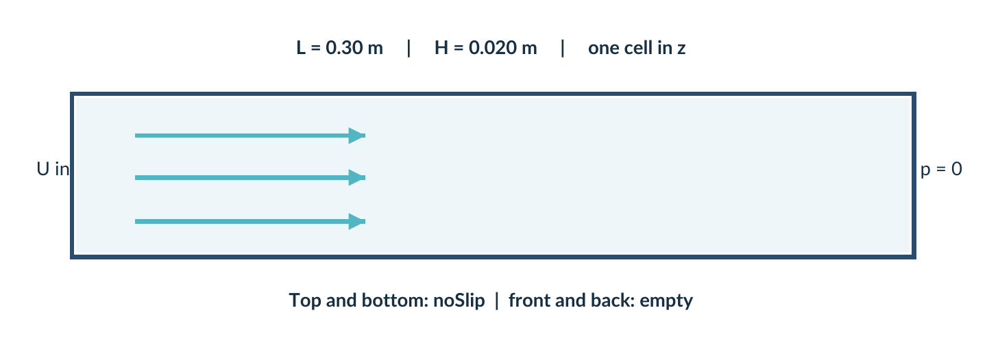
Construct a steady, laminar, incompressible, isothermal channel-flow case from an empty directory. OpenFOAM 14 and its official documentation may be consulted. Do not open the reference sections (22–27 below) until you finish a first implementation.
| Physical requirement | Value |
|---|---|
| Domain | 2D channel represented by a thin 3D block |
| Length (x) | 0.30 m |
| Height (y) | 0.020 m |
| Extruded depth (z) | 0.001 m, one cell thick |
| Nominal cells | 80 × 16 × 1 |
| Inlet velocity | U = (0.01, 0, 0) m/s |
| Outlet | Kinematic pressure reference p = 0 |
| Walls | No-slip on upper and lower boundaries |
| Front / back | empty (two-dimensional assumption) |
| Kinematic viscosity | nu = 1.0e-5 m²/s |
| Module | incompressibleFluid (Foundation 14) |
The fluid is chosen to make a modest-Reynolds-number demonstration: use channel height as the stated characteristic length and explicitly calculate the Reynolds number.
Deep dive: write these predictions before you start
As in Part 2, independent predictions written in advance are the cheapest error detector available. All values follow from the table:
| Quantity | Calculation | Prediction |
|---|---|---|
| Cell size x | 0.30 m / 80 | 3.75 mm |
| Cell size y | 0.020 m / 16 | 1.25 mm |
| Cell size z | 0.001 m / 1 | 1.0 mm |
| Cells | 80 × 16 × 1 | 1,280 |
| Points | 81 × 17 × 2 | 2,754 |
| Internal faces | 79 × 16 + 80 × 15 | 2,464 |
| Boundary faces | inlet 16 + outlet 16 + walls 2 × 80 + frontAndBack 2 × 1,280 | 2,752 |
| Total faces | 2,464 + 2,752 | 5,216 |
| Bounding box | from the vertices | (0 0 0) (0.3 0.02 0.001) |
| Flow rate | U × H × depth | 2 × 10⁻⁷ m³/s |
| Reynolds number | U H / ν | 20 (section 28) |
checkMesh should also report two geometric and two solution directions, (1 1 0): the z direction is removed by the empty patches. Any mismatch between these predictions and the logs points to a specific file.
20 Capstone: independent implementation
Build sequence
Stage A: geometry. Define eight vertices, one hex block, one-cell extrusion, four named physical patch groups and front/back empty faces. Run blockMesh and checkMesh.
Stage B: initial fields. Create 0/U and 0/p with proper headers, dimensions, internal values and complete boundaryField entries.
Stage C: physical model. Select the constant-viscosity model and laminar momentum transport in constant/.
Stage D: numerical model. Choose a steady time discretisation, momentum-convection scheme, diffusion scheme and field solvers. Explain each.
Stage E: execution. Configure system/controlDict for a 300-iteration limit and writes every 50 iterations. Run foamRun.
Expected hand-in
- A case directory that contains all necessary editable input files.
- A short README describing the role of each file.
- A copy of
checkMeshoutput and a solver log. - A configuration-decision record with evidence and the first meaningful error encountered.
- A short interpretation of U, p and the mass balance.
Validation boundary
This document provides a reference configuration but the actual solver run must be verified on your own OpenFOAM 14 installation. A page cannot substitute for running the case.
Deep dive: templates for the README and for the configuration-decision record
A note on Stage A: the reference solution (section 23) has four named patches – inlet, outlet, walls (both walls in one patch) and frontAndBack (both empty faces). “Four named physical patch groups” should be read in that sense; splitting the walls into upperWall and lowerWall, as pitzDailySteady does, is equally valid provided the field files follow. A README needs one line per file and nothing more:
step08_channel - README
Purpose      : steady laminar 2D channel, incompressibleFluid, OpenFOAM Foundation 14
0/U          : velocity; inlet fixedValue (0.01 0 0) m/s; walls noSlip; outlet zeroGradient
0/p          : kinematic pressure [m^2/s^2]; outlet fixedValue 0 (reference)
constant/physicalProperties : viscosityModel constant; nu 1e-05 m^2/s
constant/momentumTransport  : simulationType laminar
system/blockMeshDict        : 0.30 x 0.020 x 0.001 m, 80 x 16 x 1 cells, 4 patches
system/controlDict          : solver incompressibleFluid; 300 iterations; write every 50
system/fvSchemes            : steadyState; bounded Gauss upwind for div(phi,U)
system/fvSolution           : GAMG for p, smoothSolver for U, SIMPLE with relaxation
Run          : blockMesh; checkMesh; foamRun
Logs         : log.blockMesh, log.checkMesh, log.foamRun
The configuration-decision record is a table with one row per non-obvious decision, written while you work rather than afterwards:
| Decision | Alternatives considered | Choice | Evidence | Check |
|---|---|---|---|---|
| Outlet velocity condition | zeroGradient, inletOutlet | zeroGradient | UG 2.1 (pitzDailySteady outlet) | run converges, no backflow at outlet |
| Convection scheme | linear, linearUpwind, upwind | bounded Gauss upwind | UG 4.5; Part 5 | compare profile with Poiseuille |
| First meaningful error | — | e.g. a missing semicolon in 0/U | the log line | fixed; foamDictionary 0/U parses |
The interpretation of U, p and the mass balance should state: the maximum velocity and where the profile becomes parabolic; the pressure drop along the channel and its comparison with −12νU/H²; inlet and outlet flow rates and their difference (section 28).
21 Capstone: assessment and diagnostics
Before consulting the reference solution, try the following independent checks.
foamVersion
blockMesh > log.blockMesh 2>&1
checkMesh > log.checkMesh 2>&1
foamDictionary -entry solver -value \
    system/controlDict
foamDictionary -entry ddtSchemes/default -value \
    system/fvSchemes
foamRun > log.foamRun 2>&1
tail -n 45 log.foamRun
Success is more than an exit code
- Generated mesh has the expected number of cells and patches.
- Mesh boundary names correspond to all required field entries.
- The solver reads all required dictionaries and fields.
- The run produces written time directories and non-trivial U and p fields.
- Continuity and solution behaviour are reasonable for this educational case.
- The student can explain each choice and point to a source.
Assessment rule
If the run fails, the assessment remains useful: submit the exact first error, show your investigation, and isolate the cause. Independent, evidence-based diagnosis is itself an intended course outcome.
Deep dive: turning each success criterion into a command and an expected result
| Criterion | How to check | Expected for the capstone |
|---|---|---|
| Cells and patches | log.checkMesh: “cells”, patch table | 1,280 cells; inlet 16, outlet 16, walls 160, frontAndBack 2,560 faces; “Mesh OK.” |
| Names correspond | foamDictionary -entry boundaryField -keywords 0/U (and 0/p) | the same four names as the mesh |
| Dictionaries read | log.foamRun header and first iteration | no fatal error; “Selecting …” lines for viscosity and momentum transport |
| Written directories | foamListTimes | 50 100 150 200 250 300 |
| Non-trivial fields | foamDictionary -entry internalField 300/U (or ParaView) | non-uniform list; Ux up to ≈0.015 m/s; p from ≈9 × 10⁻⁴ m²/s² (or slightly more) at the inlet to 0 |
| Continuity | last “time step continuity errors” line | small, not growing |
| Explanation | README and decision record | one source per choice |
Expected ddtSchemes/default value: steadyState; expected solver value: incompressibleFluid. In the solver log the line “Solving for Uz” must not appear (the empty direction is not solved). If the run finishes but the fields are still uniform at 300, the most likely causes are a field not read from 0/ or an inlet condition that does not prescribe the expected value: go back to the six questions of section 12.
22 Reference solution A — blockMesh
Answer key · do not read until after the capstone attempt.
One valid single-block geometry is shown below. Coordinates are in metres. The patch names are used consistently in the following sections.
system/blockMeshDict — first half:
FoamFile
{
    format ascii;
    class dictionary;
    object blockMeshDict;
}

vertices
(
    (0 0 0)          (0.30 0 0)
    (0.30 0.020 0)   (0 0.020 0)
    (0 0 0.001)      (0.30 0 0.001)
    (0.30 0.020 0.001) (0 0.020 0.001)
);
blocks
(
    hex (0 1 2 3 4 5 6 7) (80 16 1)
    simpleGrading (1 1 1)
);
The boundary definition continues in the next section. This listing is a reference, not a substitute for the student’s design reasoning.
Deep dive: reading the reference geometry
No units or convertToMeters entry is present, so coordinates are read in metres (the SI default; Part 2 uses units [mm]; instead). The vertices are written two per line for compactness: their labels still follow the order in the list, 0 to 7. Vertices 0–3 lie in the plane z = 0, vertices 4–7 in z = 0.001 m, with the pairs 0–4, 1–5, 2–6, 3–7 aligned through the depth. In hex (0 1 2 3 4 5 6 7) the local directions are 0→1 (x, 80 cells), 1→2 (y, 16 cells), 0→4 (z, 1 cell); the mixed product (e₁ × e₂) · e₃ = 0.30 × 0.020 × 0.001 = 6 × 10⁻⁶ m³ is positive, so the block is right-handed and its volume is the volume of the domain. simpleGrading (1 1 1) gives uniform cells, appropriate for a laminar channel at Re = 20 on a first attempt; a refined study could cluster cells towards the walls (Part 2, section on grading).
23 Reference solution B — mesh patches
Append this to system/blockMeshDict:
boundary
(
    inlet
    {
        type patch;
        faces ((0 4 7 3));
    }
    outlet
    {
        type patch;
        faces ((1 2 6 5));
    }
    walls
    {
        type wall;
        faces ((0 1 5 4) (3 7 6 2));
    }
    frontAndBack
    {
        type empty;
        faces ((0 3 2 1) (4 5 6 7));
    }
);
mergePatchPairs ();
Why this matters
The inlet face points toward negative x and the outlet toward positive x. The front/back faces are perpendicular to z and have one cell in that direction, a requirement for this 2D representation.
Deep dive: checking face orientation and the 2D requirement
Each face is given by four vertex labels, ordered so that the right-hand rule gives a normal pointing out of the block (equivalently, clockwise when seen from inside). Verify one: for the inlet (0 4 7 3), (r₄ − r₀) × (r₇ − r₄) = (0, 0, 0.001) × (0, 0.020, 0) = (−2 × 10⁻⁵, 0, 0): pointing to −x, out of the domain. The same calculation gives +x for the outlet (1 2 6 5), −y and +y for the two wall faces, −z and +z for (0 3 2 1) and (4 5 6 7). All six faces of the block are assigned, so no face falls into a default patch.
type wall for the walls is not cosmetic: it marks them for wall-distance calculations and for wall functions if a turbulence model is later selected. type empty tells OpenFOAM that no solution is required in the direction normal to those faces; it is accepted only if the mesh is one cell thick in that direction and both opposite faces are empty, and every field must then use type empty on that patch. mergePatchPairs (); is an empty list, needed only for multi-block meshes with non-conforming interfaces; leaving it in is harmless.
24 Reference solution C — velocity and pressure
0/U — complete field example:
FoamFile
{
    format ascii;
    class volVectorField;
    object U;
}
dimensions [0 1 -1 0 0 0 0];
internalField uniform (0.01 0 0);
boundaryField
{
    inlet { type fixedValue; value uniform (0.01 0 0); }
    outlet { type zeroGradient; }
    walls { type noSlip; }
    frontAndBack { type empty; }
}
0/p — kinematic pressure for incompressibleFluid:
FoamFile
{
    format ascii;
    class volScalarField;
    object p;
}
dimensions [0 2 -2 0 0 0 0];
internalField uniform 0;
boundaryField
{
    inlet { type zeroGradient; }
    outlet { type fixedValue; value uniform 0; }
    walls { type zeroGradient; }
    frontAndBack { type empty; }
}
Deep dive: why the conditions come in complementary pairs
On each open boundary one variable is prescribed (Dirichlet, fixedValue) and the other is left free (Neumann, zeroGradient):
| Patch | U | p | Reasoning |
|---|---|---|---|
| inlet | fixedValue (0.01 0 0) | zeroGradient | The flow rate is imposed; the pressure adjusts to drive it |
| outlet | zeroGradient | fixedValue 0 | Pressure level fixed; developed flow leaves without constraint |
| walls | noSlip (U = 0) | zeroGradient | No flow through the wall, no prescribed pressure |
| frontAndBack | empty | empty | 2D constraint, must match the mesh patch type |
Fixing both U and p at the same boundary over-constrains the problem; leaving both free at all boundaries leaves the pressure level undefined (that is when pRef settings in fvSolution become necessary – not here, because the outlet fixes p = 0). For an incompressible solver only pressure differences matter, so p = 0 at the outlet is a reference, not an atmospheric value. noSlip is equivalent to fixedValue with uniform (0 0 0), written more expressively. The uniform internalField (0.01 0 0) is only the initial guess of the steady iterations. The one-line form inlet { type fixedValue; value uniform (0.01 0 0); } is the same dictionary written compactly (Part 3).
25 Reference solution D — physics and control
constant/physicalProperties:
FoamFile
{
    format ascii;
    class dictionary;
    object physicalProperties;
}
viscosityModel constant;
nu 1e-05;constant/momentumTransport:
FoamFile
{
    format ascii;
    class dictionary;
    object momentumTransport;
}
simulationType laminar;system/controlDict:
FoamFile
{
    format ascii;
    class dictionary;
    object controlDict;
}
solver incompressibleFluid;
startFrom startTime;
startTime 0;
stopAt endTime;
endTime 300;
deltaT 1;
writeControl timeStep;
writeInterval 50;
writeFormat ascii;
runTimeModifiable true;
Deep dive: what each entry does, and the variants you may meet
viscosityModel constant; selects a Newtonian fluid with constant kinematic viscosity nu; the official v14 pitzDailySteady uses exactly nu 1e-05;. v14 also accepts a value with explicit units – the User Guide example pitzDailyWater writes nu 1 [cSt]; – which foamUnits can decode. Non-Newtonian alternatives (for example the generalised-Newtonian family that contains BirdCarreau) are covered in Part 7.
simulationType laminar; selects the laminar momentum-transport model, i.e. the Newtonian viscous stress with no turbulence modelling: no further fields are needed. In controlDict, solver incompressibleFluid; tells foamRun which module to load; the time entries make 300 steady iterations (deltaT 1, endTime 300) and write every 50 (writeControl timeStep, writeInterval 50) in ASCII (writeFormat ascii, readable with any editor); runTimeModifiable true re-reads the dictionaries during the run (Part 4).
26 Reference solution E — schemes
system/fvSchemes — conservative educational starting point:
FoamFile
{
    format ascii;
    class dictionary;
    object fvSchemes;
}
ddtSchemes
{
    default steadyState;
}
gradSchemes
{
    default Gauss linear;
}
divSchemes
{
    default none;
    div(phi,U) bounded Gauss upwind;
    div((nuEff*dev2(T(grad(U))))) Gauss linear;
}
laplacianSchemes
{
    default Gauss linear corrected;
}
interpolationSchemes
{
    default linear;
}
snGradSchemes
{
    default corrected;
}
Deep dive: one line per term of the equations
| Entry | Term discretised | Comment |
|---|---|---|
ddtSchemes default steadyState | ∂/∂t | Time derivative removed: steady problem |
gradSchemes default Gauss linear | ∇p, ∇U | Gauss theorem with linear face interpolation; second order |
div(phi,U) bounded Gauss upwind | ∇·(φU), convection | First order, robust (see section 05) |
div((nuEff*dev2(T(grad(U))))) Gauss linear | ∇·(νeff dev2((∇U)ᵀ)) | Explicit part of the viscous stress |
laplacianSchemes default Gauss linear corrected | ∇·(ν∇U), ∇·(∇p) | Diffusion with non-orthogonal correction |
interpolationSchemes default linear | cell → face values | Central interpolation |
snGradSchemes default corrected | normal gradient at faces | Consistent with the Laplacian |
default none; in divSchemes forces every convection term to be listed explicitly: if one is missing, the solver stops with an error naming the missing key – exactly the term to add. The name div((nuEff*dev2(T(grad(U))))) is the literal expression the code builds for the part of the viscous stress that involves the transposed velocity gradient; for incompressible flow its divergence is formally zero (∇·(∇U)ᵀ = ∇(∇·U)), but it is kept explicitly and must be given a scheme. The official pitzDailySteady uses the same name. On an orthogonal mesh like this one, corrected costs nothing and changes nothing; on a skewed mesh it matters (Part 5).
27 Reference solution F — solution
system/fvSolution — educational steady-state example:
FoamFile
{
    format ascii;
    class dictionary;
    object fvSolution;
}
solvers
{
    p
    {
        solver GAMG;
        smoother GaussSeidel;
        tolerance 1e-7;
        relTol 0.05;
    }
    U
    {
        solver smoothSolver;
        smoother symGaussSeidel;
        tolerance 1e-8;
        relTol 0.1;
    }
}
SIMPLE
{
    nNonOrthogonalCorrectors 0;
}
relaxationFactors
{
    fields { p 0.3; }
    equations { U 0.7; }
}
These parameters are a starting configuration adapted to a simple orthogonal laminar channel; they are not universal numerical defaults.
Deep dive: the choices in fvSolution and a documented alternative
GAMG (geometric-agglomerated algebraic multigrid) with a GaussSeidel smoother solves the pressure equation, which is symmetric and elliptic: multigrid removes the long-wavelength error that simple smoothers leave behind. smoothSolver with symGaussSeidel is sufficient for the momentum components. relTol 0.05 and 0.1 stop each linear solve once the residual has fallen by that factor: in a steady run, solving each iteration exactly is wasted effort because the coefficients change at the next one. tolerance is the absolute floor.
SIMPLE is the steady pressure–velocity coupling algorithm; nNonOrthogonalCorrectors 0 is right for an orthogonal block mesh. The relaxation factors (p field 0.3, U equation 0.7) are the classic pair for standard SIMPLE, which needs p + U ≈ 1 for stability. The official pitzDailySteady uses the SIMPLEC variant instead: consistent yes; with equation relaxation 0.9 and no field relaxation of p, which usually converges in fewer iterations; it also adds residualControl to stop when residuals reach given values. Either choice is legitimate; what matters is to know which one you are using and why. No pRef entries are needed because p is fixed at the outlet.
28 Reference inspection and case audit
Check your reference files against the course goals
Run on OpenFOAM Foundation 14, in the new capstone directory:
foamDictionary system/controlDict
foamDictionary system/fvSchemes
foamDictionary system/fvSolution
foamDictionary constant/physicalProperties
foamDictionary constant/momentumTransport
blockMesh
checkMesh
foamRun
Simple physical sanity check
Using channel height H = 0.020 m as the characteristic length, U = 0.01 m/s and nu = 1e-5 m²/s: ReH = U H / nu = 20. This supports selecting a laminar illustrative regime. The precise entry-length and profile depend on geometry and inlet assumptions.
Deep dive: the numbers to compare with your run
Reynolds number. ReH = 0.01 × 0.020 / 1.0 × 10⁻⁵ = 20. For infinite parallel plates the hydraulic diameter is Dh = 2H = 0.040 m, so ReDh = 40; either way the flow is far below any transition threshold (of the order of 10³ for a channel).
Entry length. A widely used correlation for laminar plane-channel flow (Durst et al., 2005) gives Le/H ≈ 0.631/(1 + 0.044 Re) + 0.0442 Re ≈ 1.2 for Re = 20, i.e. Le ≈ 0.024 m, about 8 % of the channel length; the rougher estimate 0.05 ReDh Dh ≈ 0.08 m is more conservative. In both cases the flow is fully developed well before the outlet, which justifies zeroGradient for U there.
Developed flow. umax = 1.5 U = 0.015 m/s; kinematic pressure gradient −12νU/H² = −3.0 × 10⁻³ m/s²; over 0.30 m a fully developed estimate of the kinematic pressure drop is 9.0 × 10⁻⁴ m²/s². The computed inlet pressure will be somewhat higher, because the uniform inlet profile must first be reshaped (entrance pressure loss). The upwind scheme on 80 cells adds its own small error – which is exactly what a mesh-refinement study (worked case 2) would quantify.
Mass balance. Q = U H × depth = 0.01 × 0.020 × 0.001 = 2.0 × 10⁻⁷ m³/s. Measure it with the packaged patchFlowRate function object (User Guide 7.2):
foamPostProcess -func "patchFlowRate(name=inlet)" -latestTime
foamPostProcess -func "patchFlowRate(name=outlet)" -latestTime
Expected: about −2.0 × 10⁻⁷ m³/s at the inlet (negative: flux entering) and +2.0 × 10⁻⁷ m³/s at the outlet, with a difference at the level of the continuity errors. If your installation rejects the argument name, run foamGet patchFlowRate and read the copied file for the exact keyword: the guide uses name= on the command line and patch= with #includeFunc.
29 An unfamiliar feature: a research protocol
The following exercise extends beyond the minimum capstone: investigate a function object or boundary condition that has not appeared in this series, then explain how it is configured.
Required evidence
- Official name of the selectable object and its category.
- A v14 documentation page or
foamInfooutput. - A matching tutorial or documented example.
- The smallest complete sub-dictionary that is needed.
- The target file and the reason it belongs there.
- A check proving the object is loaded and producing the expected output.
Advanced input directives — recognise before using
You may encounter #include, macro expansion, #calc, #codeBlock, #codeStream, #codeDict and other directives. The purpose at this stage is to understand that input can be computed or included dynamically; do not add such machinery unless it solves a specific problem.
Optional theory: reading source code
For uncommon settings, inspect the corresponding header/source with foamFind and confirm the expected dictionary entries. This is not C++ development: it is evidence gathering.
Deep dive: what the directives look like, and how to see their result
All directives start with #; macros start with $. User Guide 4.2 documents the language. The listing shows the forms you are most likely to meet in tutorials:
// Examples of directives you may meet (read UG 4.2 before using any of them)
#include        "initialConditions"     // insert another file here
#includeEtc     "caseDicts/setConstraintTypes"
#includeFunc    patchFlowRate(patch=outlet)  // in system/functions
Umean           0.01;
H               0.020;
nu              1e-05;
Re              #calc "$Umean*$H/$nu";   // computed when the file is read
inlet { type fixedValue; value uniform ($Umean 0 0); }
#include inserts a file at that point; #includeEtc takes the file from the OpenFOAM etc directory; #includeFunc loads a packaged function object, with arguments. $Umean substitutes the value of another entry (scoped names such as $../H or $:subDict.key reach other levels). #calc evaluates an expression when the file is read; the #code… family compiles C++ code on the fly, which needs a working compiler and is the hardest to debug – one more reason to use it only when nothing simpler works. Whatever directive is present, this command shows the input the solver will actually receive:
foamDictionary -expand system/controlDict # shows the values after expansionA worked example of the protocol, on an object not used in this series: the wallShearStress function object. Category: function object (foamToC -functionObjects); documentation: foamInfo wallShearStress and User Guide 7.2, which shows foamPostProcess -solver incompressibleFluid -func wallShearStress; target: system/functions (or the command line, for a one-off evaluation); check: a wallShearStress field written in the time directories. For the developed capstone flow the expected kinematic wall shear stress is ν · 6U/H = 3.0 × 10⁻⁵ m²/s² on each wall – a quantitative check, not just “it ran”.
30 Graduation checklist and references
Evidence of independent competence
- I can find the responsible file for a requested change.
- I can distinguish patch type, boundary condition and initial field.
- I can identify where physical properties, schemes and algorithms are configured.
- I can query and edit dictionaries without relying on a GUI.
- I can locate valid examples and document their provenance.
- I can read an IO error and isolate its likely origin.
- I can build a simple case and explain every file in it.
Primary references — OpenFOAM Foundation 14
- v14 User Guide — contents and all chapters
- 4.7 Case management tools
- 4.2 Input/output file format
- 2.1 Backward-facing step tutorial
- OpenFOAM Foundation v14 repository
Beyond this course
The next application is to compare a simple educational case with the research case it prepares for (in the original course, a reactor): identify which files and concepts remain unchanged and which physical, geometric or numerical assumptions need a new justification. Do not transfer training values into the reactor without validation.
Deep dive: a checklist for moving from the training case to a research case
The structure of the case does not change: the same three directories, the same dictionaries, the same tools. What changes is the justification behind each value. A practical way to organise the comparison is a two-column audit of the capstone files:
| Item | Usually unchanged | Needs new justification |
|---|---|---|
| Case structure, headers, dictionary language | ✓ | |
| Diagnosis method, logs, evidence record | ✓ | |
| Geometry and mesh | Real dimensions, CAD/Gmsh workflow (worked case 3, worked case 4), mesh convergence (worked case 2) | |
| Physical properties | Measured viscosity, density, temperature dependence; possibly non-Newtonian (Part 7) | |
| Flow regime and model | Re of the real device; laminar or turbulent; 2D assumption valid or not | |
| Boundary conditions | Measured inlet flow rate and profile (worked case 6) | |
| Schemes and solvers | Second-order schemes once the setup is stable; mesh quality | |
| Computing resources | Parallel decomposition (worked case 5) | |
| Validation | Independent measurements of the device |
End of the series
With this part the case-construction series is complete. The path closes where it began: Part 1 – case anatomy and the dictionary language introduced the grammar that foamDictionary parses and that every error message of section 12 refers to. Reading it again now, after building a case from an empty directory, is a good test of how much of it has become automatic.
All parts, the six worked cases and the videos are collected on the project page Learning OpenFOAM 14.