

OpenFOAM 14 Case 01: Laminar Flow Between Parallel Plates, Validated Against Poiseuille
This is the first case of the Learning OpenFOAM 14 path: steady, incompressible laminar flow between two parallel plates. I chose it on purpose because it has an exact solution, the Poiseuille profile, so the numerical result can be checked with numbers and not just by eye. In the end the computed profile matches the theoretical one to within 0.2%.
What follows is the complete reproducible procedure for the case, with analytical validation and ParaView visualization, in the same order as the original handout: OpenFOAM 14 (Foundation / CFD Direct) and ParaView 5.13.2.
1. Purpose and expected result
This handout describes the complete procedure required to build, run, validate and visualize a steady two-dimensional incompressible laminar flow between two parallel no-slip plates using OpenFOAM 14.
The case is deliberately simple because it has a closed-form Poiseuille solution. The numerical result can therefore be checked quantitatively rather than only visually.
Main target results:
| Quantity | Value |
|---|---|
| OpenFOAM version | 14 |
| Solver module | incompressibleFluid via foamRun |
| Mesh | 200 × 40 × 1 = 8,000 hexahedral cells |
| Mean inlet velocity | 0.010 m/s |
| Kinematic viscosity | 1.0e-6 m²/s |
| Hydraulic-diameter Reynolds number | Re = 200 |
| Final steady iteration label | 2000 |
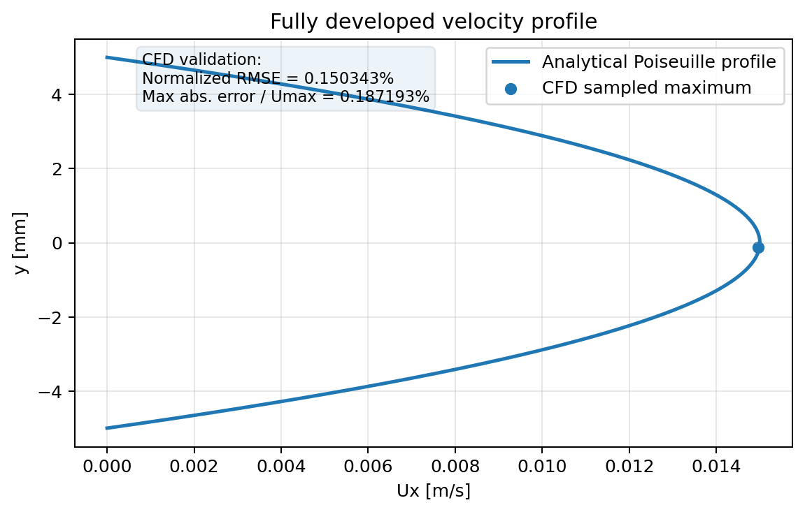
| CFD sampled maximum Ux | 0.014962547 m/s |
| Analytical maximum Ux | 0.015000000 m/s |
| Normalized RMSE | 0.150343 % |
| Maximum absolute error / Umax | 0.187193 % |
| Visualization | ParaView 5.13.2 client-server using pvserver |
The accepted numerical solution reproduces the analytical Poiseuille profile to substantially better than 0.2% over the sampled cross-section.
2. Prerequisites
The following commands should be available:
foamVersion
command -v blockMesh
command -v checkMesh
command -v foamRun
command -v foamPostProcess
command -v pvserver
Expected OpenFOAM version:
14The environment should define $FOAM_RUN. The case in this handout is created under:
$FOAM_RUN/01_laminar_channel3. Physical model
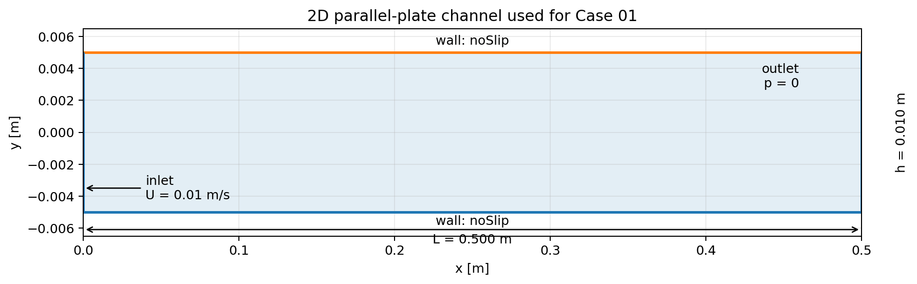
Channel dimensions:
| Parameter | Value |
|---|---|
| Channel length L | 0.500 m |
| Plate spacing H | 0.010 m |
| Numerical depth | 0.001 m |
| Front/back condition | empty |
Fluid and inlet conditions:
| Parameter | Value |
|---|---|
| Kinematic viscosity ν | 1.0e-6 m²/s |
| Mean inlet velocity Umean | 0.010 m/s |
The hydraulic diameter for two wide parallel plates is approximately
Dh = 2H = 0.020 m
and therefore
Re = Umean·Dh / ν = (0.01 · 0.02) / 10⁻⁶ = 200.
The flow is intentionally well inside the laminar regime.
4. Create the case directory
mkdir -p $FOAM_RUN/01_laminar_channel/{0,constant,system}
cd $FOAM_RUN/01_laminar_channel
5. Mesh definition
Create system/blockMeshDict:
FoamFile
{
    format      ascii;
    class       dictionary;
    object      blockMeshDict;
}

scale 1;

vertices
(
    (0.0  -0.005  0.0)
    (0.5  -0.005  0.0)
    (0.5   0.005  0.0)
    (0.0   0.005  0.0)

    (0.0  -0.005  0.001)
    (0.5  -0.005  0.001)
    (0.5   0.005  0.001)
    (0.0   0.005  0.001)
);

blocks
(
    hex (0 1 2 3 4 5 6 7) (200 40 1) simpleGrading (1 1 1)
);

edges
(
);

boundary
(
    inlet
    {
        type patch;
        faces
        (
            (0 4 7 3)
        );
    }

    outlet
    {
        type patch;
        faces
        (
            (1 2 6 5)
        );
    }

    walls
    {
        type wall;
        faces
        (
            (0 1 5 4)
            (3 7 6 2)
        );
    }

    frontAndBack
    {
        type empty;
        faces
        (
            (0 3 2 1)
            (4 5 6 7)
        );
    }
);

mergePatchPairs
(
);
The structured mesh contains
200 × 40 × 1 = 8000
hexahedral cells.
6. Run control
Create system/controlDict before running the mesh utilities:
FoamFile
{
    format      ascii;
    class       dictionary;
    location    "system";
    object      controlDict;
}

solver          incompressibleFluid;

startFrom       startTime;
startTime       0;

stopAt          endTime;
endTime         2000;

deltaT          1;

writeControl    runTime;
writeInterval   200;

purgeWrite      0;

writeFormat     ascii;
writePrecision  8;
writeCompression off;

timeFormat      general;
timePrecision   6;

runTimeModifiable true;
Because the case uses steadyState in fvSchemes, the values 1…2000 are iteration/pseudo-time labels, not a 2000-second physical transient.
7. Generate and verify the mesh
blockMesh | tee log.blockMesh
checkMesh | tee log.checkMesh
Useful check:
grep -E "points:|faces:|cells:|hexahedra:|Mesh OK" log.checkMeshExpected result:
cells:          8000
hexahedra:      8000
Mesh OK.
8. Initial and boundary fields
8.1 Velocity field: 0/U
FoamFile
{
    format      ascii;
    class       volVectorField;
    location    "0";
    object      U;
}

dimensions      [velocity];

internalField   uniform (0 0 0);

boundaryField
{
    inlet
    {
        type            fixedValue;
        value           uniform (0.01 0 0);
    }

    outlet
    {
        type            zeroGradient;
    }

    walls
    {
        type            noSlip;
    }

    frontAndBack
    {
        type            empty;
    }
}
8.2 Pressure field: 0/p
FoamFile
{
    format      ascii;
    class       volScalarField;
    location    "0";
    object      p;
}

dimensions      [kinematicPressure];

internalField   uniform 0;

boundaryField
{
    inlet
    {
        type            zeroGradient;
    }

    outlet
    {
        type            fixedValue;
        value           uniform 0;
    }

    walls
    {
        type            zeroGradient;
    }

    frontAndBack
    {
        type            empty;
    }
}
9. Fluid properties and laminar model
9.1 constant/physicalProperties
FoamFile
{
    format      ascii;
    class       dictionary;
    location    "constant";
    object      physicalProperties;
}

viscosityModel  constant;

nu              1e-06;
9.2 constant/momentumTransport
FoamFile
{
    format      ascii;
    class       dictionary;
    location    "constant";
    object      momentumTransport;
}

simulationType  laminar;
10. Numerical schemes
Create system/fvSchemes:
FoamFile
{
    format      ascii;
    class       dictionary;
    location    "system";
    object      fvSchemes;
}

ddtSchemes
{
    default         steadyState;
}

gradSchemes
{
    default         Gauss linear;
}

divSchemes
{
    default         none;
    div(phi,U)      bounded Gauss linearUpwind grad(U);
    div((nuEff*dev2(T(grad(U))))) Gauss linear;
}

laplacianSchemes
{
    default         Gauss linear corrected;
}

interpolationSchemes
{
    default         linear;
}

snGradSchemes
{
    default         corrected;
}
11. Linear solvers and pressure-velocity coupling
Create system/fvSolution:
FoamFile
{
    format      ascii;
    class       dictionary;
    location    "system";
    object      fvSolution;
}

solvers
{
    p
    {
        solver          PCG;
        preconditioner  DIC;
        tolerance       1e-10;
        relTol          0.05;
    }

    pFinal
    {
        $p;
        relTol          0;
    }

    U
    {
        solver          smoothSolver;
        smoother        symGaussSeidel;
        tolerance       1e-10;
        relTol          0.05;
    }

    UFinal
    {
        $U;
        relTol          0;
    }
}

PIMPLE
{
    momentumPredictor        no;
    nOuterCorrectors         1;
    nNonOrthogonalCorrectors 0;
}

relaxationFactors
{
    fields
    {
        p   0.3;
    }

    equations
    {
        U   0.7;
    }
}
12. Execute the CFD calculation
Run a final mesh check and start the solver:
checkMesh
foamRun | tee log.foamRun
Inspect the final iterations:
tail -40 log.foamRunThe validated run reached the final iteration label 2000 and terminated normally with End.
Typical final behavior:
| Quantity | Observed behavior |
|---|---|
| Execution time | approximately 27.7 s |
| Pressure initial residual | order 1e-10 |
| Pressure iterations | often 0–1, occasionally a few |
| Local continuity error | order 1e-12 |
| Termination | normal End |
13. Analytical Poiseuille solution
For fully developed laminar flow between parallel plates, the analytical velocity profile is
u(y) = (3/2)·Umean·[1 − (2y/H)²].
With Umean = 0.010 m/s and H = 0.010 m:
Umax,theory = 1.5·Umean = 0.015 m/s.
14. Velocity-profile post-processing
Create system/graphUniform:
FoamFile
{
    format      ascii;
    class       dictionary;
    object      graphUniform;
}

start           (0.45 -0.004875 0.0005);
end             (0.45  0.004875 0.0005);
nPoints         40;

fields          (U);

axis            y;

#includeEtc "caseDicts/postProcessing/graphs/graphUniform.cfg"
Run the function object explicitly:
foamPostProcess -solver incompressibleFluid -func graphUniform -latestTimeLocate the result:
find postProcessing/graphUniform -type fExpected file:
postProcessing/graphUniform/2000/line.xyInspect it:
head -10 postProcessing/graphUniform/2000/line.xy
tail -10 postProcessing/graphUniform/2000/line.xy
wc -l postProcessing/graphUniform/2000/line.xy
The file contains one header plus 40 sampled points. Its columns are:
y U_x U_y U_zRepresentative values:
| y [m] | CFD Ux [m/s] | Uy [m/s] |
|---|---|---|
| -0.004875 | 0.00073033707 | -5.38e-17 |
| -0.004125 | 0.0047752809 | -2.79e-16 |
| -0.003125 | 0.0091198502 | -4.20e-16 |
| -0.002875 | 0.010018726 | -5.09e-16 |
| +0.002875 | 0.010018726 | -2.82e-15 |
| +0.003875 | 0.0059737828 | -4.36e-15 |
| +0.004875 | 0.00073033707 | -7.37e-16 |
The transverse velocity is effectively zero and Uz is zero, as expected for this 2D channel.
15. Quantitative validation script
The following command compares every sampled point with the analytical Poiseuille profile:
awk '
BEGIN {
    H=0.01
    Umean=0.01
    UmaxTheory=1.5*Umean
    umax=-1
}
$1 !~ /^#/ && NF >= 4 {
    y=$1
    u=$2

    uth=UmaxTheory*(1-(2*y/H)^2)

    e=u-uth
    ae=(e<0 ? -e : e)

    sumsq += e*e
    n++

    if (ae > maxerr) {
        maxerr=ae
        maxerr_y=y
        maxerr_cfd=u
        maxerr_theory=uth
    }

    if (u > umax) {
        umax=u
        umax_y=y
    }
}
END {
    rmse=sqrt(sumsq/n)

    printf "Points              : %d\n", n
    printf "CFD maximum Ux      : %.10f m/s\n", umax
    printf "Location of max     : %.7f m\n", umax_y
    printf "Theoretical Umax    : %.10f m/s\n", UmaxTheory
    printf "RMSE                : %.10e m/s\n", rmse
    printf "Normalized RMSE     : %.6f %%\n", 100*rmse/UmaxTheory
    printf "Maximum abs error   : %.10e m/s\n", maxerr
    printf "Max error / Umax    : %.6f %%\n", 100*maxerr/UmaxTheory
    printf "Max-error y         : %.7f m\n", maxerr_y
    printf "CFD there           : %.10f m/s\n", maxerr_cfd
    printf "Theory there        : %.10f m/s\n", maxerr_theory
}' postProcessing/graphUniform/2000/line.xy
Validated result:
| Metric | Value |
|---|---|
| Points compared | 40 |
| CFD maximum Ux | 0.0149625470 m/s |
| Location of CFD maximum | y = -0.0001250 m |
| Theoretical Umax | 0.0150000000 m/s |
| RMSE | 2.2551518927e-05 m/s |
| Normalized RMSE | 0.150343 % |
| Maximum absolute error | 2.8079000000e-05 m/s |
| Maximum error / Umax | 0.187193 % |
| Location of maximum error | y = +0.0001250 m |
| CFD value at max-error point | 0.0149625460 m/s |
| Theory at same point | 0.0149906250 m/s |
The sampling uses 40 points, therefore the centerline y = 0 is not sampled exactly. The closest samples are approximately at y = ±0.000125 m.
16. Pressure verification
For plane Poiseuille flow, the expected kinematic-pressure gradient is
dp/dx = −12·ν·Umean / H² = −1.2 × 10⁻³ m/s².
Across 0.5 m, the corresponding kinematic pressure drop is approximately
6 × 10⁻⁴ m²/s²,
or approximately 0.6 Pa for water with ρ ≈ 1000 kg/m³.
To sample pressure along the developed region, temporarily use the following system/graphUniform:
FoamFile
{
    format      ascii;
    class       dictionary;
    object      graphUniform;
}

start           (0.30 0 0.0005);
end             (0.49 0 0.0005);
nPoints         40;

fields          (p);

axis            x;

#includeEtc "caseDicts/postProcessing/graphs/graphUniform.cfg"
Then run:
foamPostProcess -solver incompressibleFluid -func graphUniform -latestTimeThe sampled pressure should decrease approximately linearly in the fully developed region.
17. ParaView client-server visualization
For interactive visualization, use ParaView in client-server mode.
17.1 Start the server
Check the installed version:
command -v pvserver
pvserver --version
Validated version:
paraview version 5.13.2Create the OpenFOAM marker file:
cd $FOAM_RUN/01_laminar_channel
touch 01_laminar_channel.foam
Start pvserver:
pvserver --bind-address=0.0.0.0 --server-port=1111117.2 Connect from ParaView on the workstation
Use the same ParaView version as the server: 5.13.2.
In ParaView:
File -> Connect... -> Add ServerConfigure:
Name: CFD Server
Server Type: Client / Server
Host: <server IP address>
Port: 11111
After connecting, File → Open browses the remote Linux filesystem. Open:
$FOAM_RUN/01_laminar_channel/01_laminar_channel.foamSelect internalMesh, enable U and p, then press Apply.
17.3 Visual checks
At the final iteration label 2000:
- Coloring → U → Magnitude
- Rescale to Data Range
- verify a symmetric velocity distribution with maximum velocity at the channel center and zero velocity at the no-slip walls
- Coloring → p
- verify a regular pressure decrease from inlet to outlet
For a clean streamline view, the channel may be displayed as Outline, or as a low-opacity surface.
18. Streamlines
Select the OpenFOAM source and create:
Filters -> Stream TracerRecommended settings:
| Property | Value |
|---|---|
| Vectors | U |
| Integration Direction | FORWARD |
| Seed Type | Line |
| Point1 | (0.001, -0.0045, 0.0005) |
| Point2 | (0.001, +0.0045, 0.0005) |
| Resolution | 20 |
| Maximum Streamline Length | 0.5 m |
Resolution here controls the number of seed intervals along the seed line; it is not the CFD mesh resolution.
For this steady case the streamlines coincide with particle trajectories. They should be straight and parallel to the x direction.
19. Generic troubleshooting
| Symptom | Check / correction |
|---|---|
blockMesh or checkMesh cannot start the case | ensure system/controlDict exists |
foamPostProcess creates no postProcessing directory | call the function explicitly with -func graphUniform |
expected line_U.xy is not present | OpenFOAM 14 writes line.xy for this configuration |
graphUniform include is not found | use caseDicts/postProcessing/graphs/graphUniform.cfg |
| only a small number of streamlines appears | verify that the entire seed line lies inside the CFD domain |
| streamline view is visually cluttered | display the CFD source as Outline or reduce surface opacity |
20. Acceptance criteria
| Acceptance criterion | Status |
|---|---|
| OpenFOAM environment operational | PASS |
Mesh generated and checkMesh successful | PASS |
Steady calculation reaches normal End | PASS |
| Velocity profile symmetric | PASS |
| Uy negligible and Uz = 0 | PASS |
| Normalized RMSE < 0.2% | PASS – 0.150343% |
| Pressure decreases along the channel | PASS |
| ParaView client-server visualization operational | PASS |
| Streamlines span the channel and remain parallel to x | PASS |
Final status: CASE 01 COMPLETE AND VALIDATED.
21. Reproducibility checklist
- Source the OpenFOAM 14 environment.
- Create
$FOAM_RUN/01_laminar_channel. - Create
blockMeshDictandcontrolDict. - Run
blockMeshandcheckMesh. - Create
0/Uand0/p. - Create
constant/physicalPropertiesandconstant/momentumTransport. - Create
fvSchemesandfvSolution. - Run
foamRun | tee log.foamRun. - Sample U at x = 0.45 m with
graphUniform. - Compare the sampled profile against Poiseuille theory.
- Optionally sample p along x and compare with the analytical pressure gradient.
- Create the
.foammarker file. - Start
pvserverand connect from ParaView 5.13.2. - Inspect U, p and streamlines at the final iteration label.
This case is the validated baseline for the subsequent CFD training simulations: in Case 02 the same channel is used for a mesh convergence study.