

OpenFOAM 14 Part 2: Building a Mesh with blockMeshDict
Part 2 of 8 of the case-construction series in the Learning OpenFOAM 14 path: from geometry to a verified volume mesh.
The task. Construct a three-dimensional channel from eight vertices, choose its cell distribution, assign every boundary face, and verify the generated mesh.
The result. A complete system/blockMeshDict, a minimal mesh-only case, and a method for reading the corresponding official documentation.
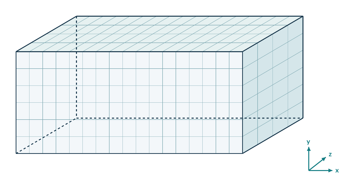
How to use this part
Part 1 introduced the language and the conceptual trainingChannel directory. This part turns that name into a concrete mesh. It belongs to the dictionary-construction series, not to the initial practical cases.
Keep a terminal and this article side by side. Read the geometry and ordering sections first; then type the complete files in sections 10 and 11. The answer notes are in section 20, after the exercises.
| Reading route | Sections | What you will do |
|---|---|---|
| Specify and describe | 1–4 | Set dimensions, label vertices and define a right-handed block. |
| Distribute cells | 5–7 | Choose resolution and understand one-way or symmetric grading. |
| Name the boundary | 8–9 | Separate patch identity, mesh type and face ordering. |
| Build and inspect | 10–15 | Create the two files, generate the mesh and compare predictions. |
| Work independently | 16–20 | Modify, diagnose and construct a second channel. |
| Use the documentation | 21 and references | Find syntax, examples and primary references. |
Main outcome
You should be able to explain how every major section of blockMeshDict changes the geometry, topology, cell distribution or patch assignment. A working file without that explanation is not the endpoint.
Scope and prerequisites
Use a Bash shell with Foundation OpenFOAM 14 loaded, and your own writable case directory. You need basic editing and navigation, plus the dictionary syntax from Part 1. No C++ development, CAD model, turbulence model or flow solver is required here.
Optional recall boxes
Recall boxes contain background or derivations. They can be skipped without interrupting the main practical route.
Documentation: Part 1, §1.1 and §B.1. Public references [R1]–[R10] are listed at the end of the article.
1. Specify the channel before typing
The example is a three-dimensional rectangular duct. Its intended flow direction is +x. All four long faces are walls; the x-normal end faces are the inlet and outlet. These are teaching choices, not reactor dimensions or experimentally validated settings.
| Quantity | Input value | Meaning |
|---|---|---|
| Length L | 100 mm | x: from inlet to outlet |
| Height H | 10 mm | y: between the lower and upper walls |
| Depth W | 5 mm | z: between the two side walls |
| Cells | 40 × 10 × 5 | Local x, y and z directions |
| Grading | 1 × 1 × 1 | Initially uniform along each direction |
| Patch names | inlet / outlet / walls | The names carried into later field files |
Write these predictions first
The bounding box in the default SI system is (0 0 0) to (0.1 0.01 0.005) m. There are 2,000 cells. The volume is 5 × 10⁻⁶ m³. You will use these independent predictions to catch unit and resolution errors.
Documentation: [R1], §§5.4.2–5.4.5. Numerical values and geometry in this part are original teaching examples.
2. The file is a recipe, not the mesh
blockMesh reads the block description, creates cells and connectivity, and writes a mesh into constant/polyMesh/. The eight block vertices are control points for the construction; they are not the full list of generated mesh points.
system/blockMeshDict
        |
        |  blockMesh
        v
constant/polyMesh/
points faces owner neighbour boundary| Entry | How to read it | Role in this lesson |
|---|---|---|
FoamFile | A sub-dictionary in braces | Identifies a dictionary object named blockMeshDict. |
units | A length-unit entry | Interprets input coordinates as millimetres. |
vertices | A parenthesised list | Supplies the eight corner coordinates. |
blocks | A parenthesised list | Defines connectivity, cell counts and grading. |
boundary | A list of named sub-dictionaries | Assigns the six exterior block faces to patches. |
Read punctuation as structure
A vector such as (100 10 5) is a list of components. A vertices (...); entry ends with a semicolon after the closing parenthesis. Each patch body uses braces. The boundary entry itself is a list, not a single brace-enclosed sub-dictionary.
Omitted on purpose
Straight edges need no edges entry. This one-block case also needs no mergePatchPairs. No exterior face will be left to an implicit default patch. Add a feature only when the geometry requires it.
Documentation: [R1], §§5.4.1, 5.4.4, 5.4.7–5.4.8; [R2]; dictionary grammar: [R4].
3. Vertices: labels are list positions
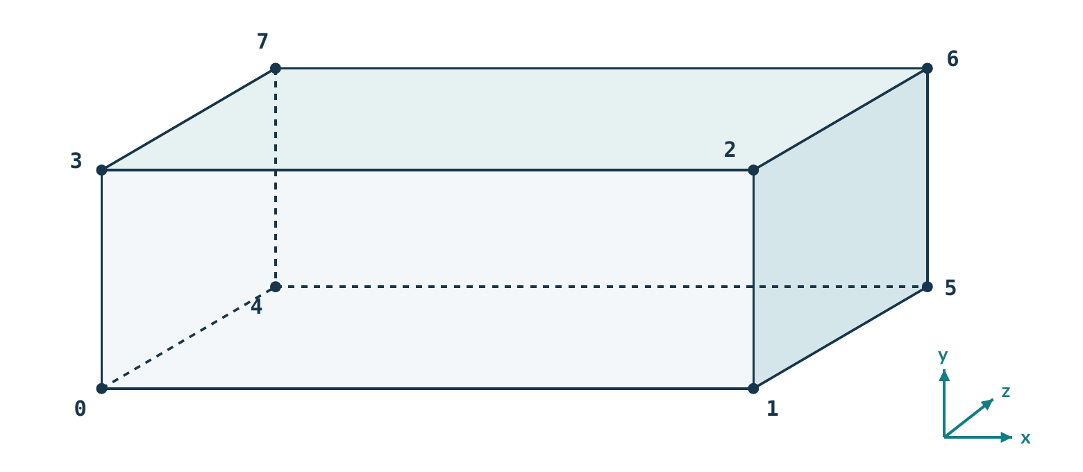
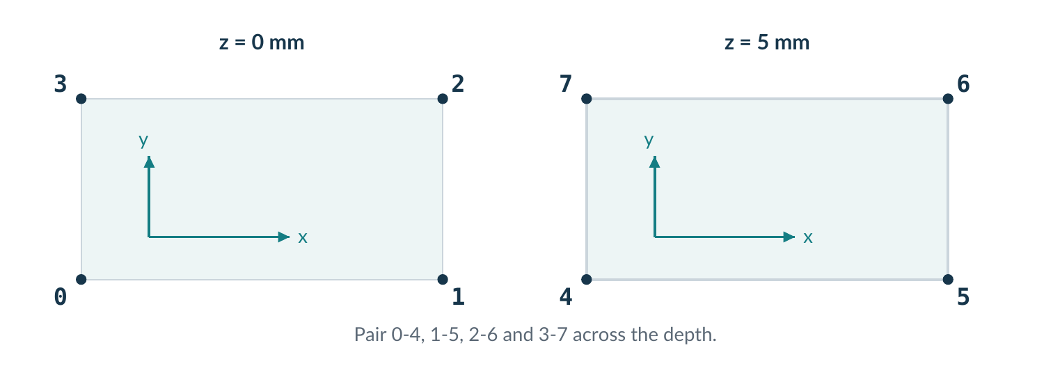
The first entry in vertices has label 0, the second label 1, and so on. Comments are reminders for the reader; the comments do not assign the labels. Reordering the list changes the meaning of all references to it.
units [mm];

vertices
(
    (  0   0  0)   // 0
    (100   0  0)   // 1
    (100  10  0)   // 2
    (  0  10  0)   // 3
    (  0   0  5)   // 4
    (100   0  5)   // 5
    (100  10  5)   // 6
    (  0  10  5)   // 7
);
A quick consistency check
Vertices 0-3 lie at z = 0; vertices 4-7 lie at z = 5 mm. Each pair across the depth differs only in z. The x coordinates take only 0 or 100; the y coordinates take only 0 or 10.
Units: convert once
With units [mm];, enter 100 for 100 mm, not 0.1. The generated mesh uses the base length unit, metre in the default SI setup. Do not also add a millimetre-to-metre scale factor to this example.
Documentation: [R1], §§5.4.2–5.4.3; [R4], units and list syntax.
4. The hex order defines local directions
blocks
(
    hex (0 1 2 3 4 5 6 7) (40 10 5)
    simpleGrading (1 1 1)
);
hex describes a hexahedral block. The first four labels trace one quadrilateral; the next four are its corresponding vertices across the third direction. In this particular rectangular block, the local directions coincide with global x, y and z.
| Local direction | How to identify it here | Controls |
|---|---|---|
| 1: +x | 0 → 1 | 40 cells; first grading value |
| 2: +y | 1 → 2 (parallel to 0 → 3) | 10 cells; second grading value |
| 3: +z | 0 → 4 | 5 cells; third grading value |
Why the order cannot be arbitrary
The block must be right-handed. For this rectangular example, take e₁ = r₁ − r₀, e₂ = r₃ − r₀, and e₃ = r₄ − r₀. Their scalar triple product is positive. An arbitrary swap of labels can invert or twist the block instead of merely renaming its corners.
Optional recall / right-handedness
For this parallelepiped, (e₁ × e₂) · e₃ = LHW = 5,000 mm³ > 0. The sign checks orientation; the value is its volume. This single corner calculation is not a general quality test for a curved or warped hexahedron.
Separate a block from its cells
One hex entry does not mean one computational cell. It describes the region that will be subdivided into 40 × 10 × 5 = 2,000 cells. Rotating a block can change the relation between local cell-count directions and the global axes.
Documentation: [R1], §5.4.5; [R8], built-in block-ordering description. Triple-product calculation: derived for this example.
5. Resolution is independent of size
Coordinates set the physical domain. Cell counts set how finely that domain is divided. With uniform grading, the reference cell sizes are obtained directly from the three lengths.
| Direction | Calculation | Cell size |
|---|---|---|
| x | 100 mm / 40 | 2.5 mm |
| y | 10 mm / 10 | 1.0 mm |
| z | 5 mm / 5 | 1.0 mm |
Predict before you change the file
| Change | Cell count | What stays the same |
|---|---|---|
| Baseline: (40 10 5) | 2,000 | Reference domain and patches |
| Only x: (80 10 5) | 4,000 | Domain size; y and z cell widths |
| All directions: (80 20 10) | 16,000 | Domain size and patch locations |
| Double L; keep (40 10 5) | 2,000 | Topology; x cells become twice as long |
Doubling the counts in three directions multiplies the number of cells by eight. That arithmetic alone does not specify the increase in simulation time, which also depends on the solver, time step and convergence behaviour.
Optional recall / cells are control volumes
A finite-volume method balances quantities over cells and exchanges fluxes through their faces. Refinement changes the spatial approximation; it does not add new physical dimensions to the problem. A mesh that passes geometric checks can still be too coarse for the quantity of interest.
Do not turn a 3D duct into a 2D model accidentally
The baseline has five cells through its depth and wall patches on both z-faces. A one-cell-thick mesh is not automatically a valid two-dimensional model. An empty direction requires compatible geometry and matching field conditions; it is not used in this lesson.
Documentation: [R1], §5.4.5; two-dimensional constraints: [R3]. All counts in the tables are analytical predictions.
6. Grading: end cell divided by start cell
For a direction with N cells, simpleGrading uses the overall expansion ratio E = Δlast/Δfirst. It is not the ratio between neighbouring cells. Here the y-direction runs from the lower wall at y = 0 to the upper wall at y = H.
simpleGrading (1 4 1)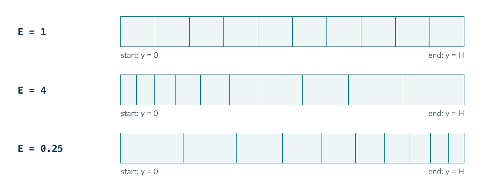
For H = 10 mm, N = 10 and E = 4, the first cell is about 0.4542 mm wide and the last is about 1.8170 mm. The number of cells and the overall height remain unchanged.
Optional recall / geometric progression
With N > 1, neighbouring widths have ratio q = E1/(N−1). For q ≠ 1, Δfirst = H(q − 1)/(qN − 1). For E = 1, use Δ = H/N. In this example q ≈ 1.1665, not 4.
A useful prediction
Changing (1 1 1) to (1 4 1) refines near y = 0 and coarsens near y = H. It does not refine both walls. Changing it to (1 0.25 1) reverses that distribution.
Documentation: [R1], §5.4.5. Cell-width calculations and Figure 3 follow the geometric progression above.
7. Optional: refine towards both walls
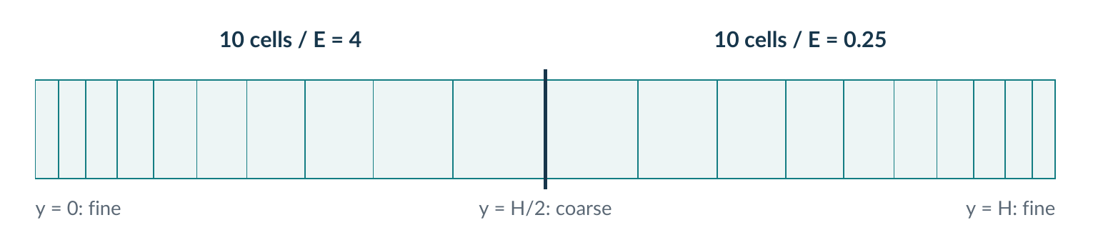
A single ratio gives one-way grading. To keep a single block but refine towards both y-walls, split the y-direction into two grading sections. This optional example uses 20 cells in y instead of the baseline 10.
blocks
(
    hex (0 1 2 3 4 5 6 7) (40 20 5)
    simpleGrading
    (
        1
        (
            (0.5 0.5 4)
            (0.5 0.5 0.25)
        )
        1
    )
);
Each inner triple means (fraction of length, fraction of cells, expansion ratio). The lower half occupies 50% of the height and gets 50% of the 20 y-cells. The upper half does the same, with the reciprocal expansion.
What to verify
The new mesh contains 4,000 cells and has the same bounding box. Cell widths near either y-wall are about 0.2271 mm; the two centre-adjacent widths are about 0.9085 mm. These values describe this example only.
Keep the main route simple
Use the uniform baseline in section 10 for your first successful build. This extension introduces nested lists and grading towards two opposing walls; it does not introduce near-wall resolution requirements for turbulence models.
Documentation: [R1], §5.4.6. The two-section example and numerical values are constructed for this part.
8. A patch has a name and a mesh type
A boundary patch groups exterior faces. The name is an identifier you choose; the mesh type describes the kind of patch. Neither alone prescribes the inlet velocity or the pressure at the outlet.
| Patch name | Mesh type | Faces included |
|---|---|---|
inlet | patch | The end face at x = 0 |
outlet | patch | The end face at x = L |
walls | wall | Both y-faces and both z-faces |
A fragment inside the boundary list, not a complete file:
inlet
{
    type patch;
    faces ((0 4 7 3));
}
The outer parentheses after faces hold a list of faces. The inner parentheses hold the four vertex labels of this one block face. The walls patch uses the same syntax but contains four faces.
Mesh description versus field condition
| In the mesh dictionary | Later, in a field file |
|---|---|
walls { type wall; ... } | U may impose noSlip on the walls patch. |
inlet { type patch; ... } | U may prescribe a velocity there; p has its own condition. |
The future 0/U and 0/p files will refer to these patch names. Part 3 explains those field conditions. For now, create no velocity or pressure file merely to make a meshing command run.
Why group four faces?
All four long faces have the same mesh type and will initially share their field conditions. Separate them into distinct patches later only when a boundary condition or measurement needs that distinction. Patch grouping changes identity, not cell resolution.
Documentation: [R1], §5.4.7; mesh constraints and types: [R3].
9. Walk around each face edge by edge
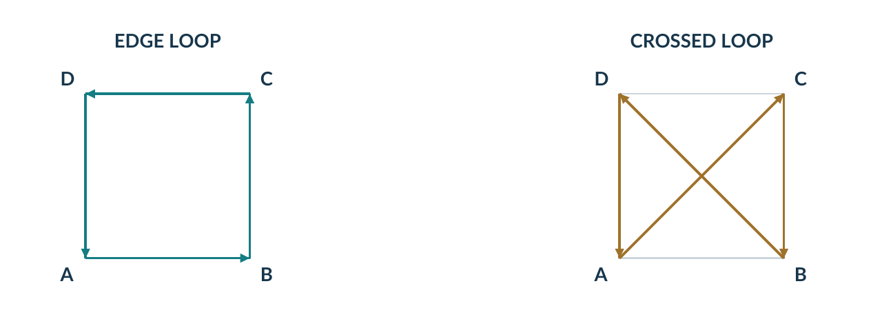
A face entry is a loop through four connected corners, not a set of four labels in arbitrary order. The table below uses outward-oriented loops for clarity. Together they account for all six exterior faces of the block.
| Location | Loop in blockMeshDict | Outward normal | Patch |
|---|---|---|---|
| x = 0 | (0 4 7 3) | −x | inlet |
| x = L | (1 2 6 5) | +x | outlet |
| y = 0 | (0 1 5 4) | −y | walls |
| y = H | (3 7 6 2) | +y | walls |
| z = 0 | (0 3 2 1) | −z | walls |
| z = W | (4 5 6 7) | +z | walls |
Important v14 distinction
The v14 guide permits either direction around a blockMeshDict boundary face, provided consecutive vertices follow connected edges. Outward ordering here is a teaching convention, not an extra parser requirement. The generated polyMesh uses its own consistent owner/neighbour face orientation.
For a check on this rectangular example, the cross product of successive edges in the inlet loop points in −x. Reversing that whole loop changes the hand calculation of its normal, but does not justify predicting a blockMesh failure. Crossing diagonals, omitting a face or using the wrong labels is a different issue.
Documentation: [R1], §5.4.7, especially the direction convention; generated face orientation: [R2].
10. The complete blockMeshDict
Save this entire listing as system/blockMeshDict. It has no omitted sections or line numbers. The minimal controlDict is in the next section.
FoamFile
{
    format      ascii;
    class       dictionary;
    object      blockMeshDict;
}

units [mm];

vertices
(
    (  0   0  0)   // 0
    (100   0  0)   // 1
    (100  10  0)   // 2
    (  0  10  0)   // 3
    (  0   0  5)   // 4
    (100   0  5)   // 5
    (100  10  5)   // 6
    (  0  10  5)   // 7
);

blocks
(
    hex (0 1 2 3 4 5 6 7) (40 10 5)
    simpleGrading (1 1 1)
);

boundary
(
    inlet
    {
        type patch;
        faces ((0 4 7 3));
    }

    outlet
    {
        type patch;
        faces ((1 2 6 5));
    }

    walls
    {
        type wall;
        faces
        (
            (0 1 5 4)
            (3 7 6 2)
            (0 3 2 1)
            (4 5 6 7)
        );
    }
);
Documentation: [R1], standard v14 syntax. This complete reference dictionary is an original teaching example.
11. Supply a minimal run-time context
OpenFOAM utilities initialise a run-time object. Supply system/controlDict even though you are not solving a flow. The following values are a mesh-only scaffold, not the time-step choice for the later CFD simulation.
FoamFile
{
    format      ascii;
    class       dictionary;
    object      controlDict;
}

application       blockMesh;
startFrom         startTime;
startTime         0;
stopAt            endTime;
endTime           1;
deltaT            1;
writeControl      timeStep;
writeInterval     1;
writeFormat       ascii;
writePrecision    10;
writeCompression  off;
timeFormat        general;
timePrecision     6;
runTimeModifiable yes;
What is being selected?
The shell command selects the program you execute. The application blockMesh; entry documents the purpose of this scaffold; it does not cause checkMesh to run blockMesh. Detailed time and output controls belong to Part 4.
What is still absent?
The standalone blockMesh and basic checkMesh workflow does not need fvSchemes, fvSolution, physical properties, U or p. Those files will be added when their consuming application needs them.
Do not run foamRun yet
A valid mesh is not a complete flow case. The goal at this stage is to generate and inspect polyMesh, then carry its patch names into the next part.
Documentation: [R5]; utility run-time construction and mesh-only reads: [R8]–[R9].
12. Generate, then inspect the real log
Prepare a new working directory
Use your own home directory, not the installed tutorial tree. Execute each step separately and stop on an error. If the named case already exists, inspect it before editing or choose a new name.
foamVersion
command -v blockMesh checkMesh foamDictionary
mkdir -p ~/cases/dictionary-training
cd ~/cases/dictionary-training
mkdir trainingChannel
cd trainingChannel
mkdir 0 constant system
vi system/blockMeshDict
vi system/controlDict
The version must identify Foundation release 14. Enter the full listings from sections 10 and 11. In vi, save and quit with :wq. An empty 0/ directory is sufficient at this stage.
Run one command at a time from the case root
set -o pipefail
blockMesh 2>&1 | tee log.blockMesh
checkMesh -constant 2>&1 | tee log.checkMesh
Run checkMesh only after mesh generation succeeds. Read the actual report for counts, dimensions and the final check summary. For the uniform rectangular reference mesh, the target is Mesh OK. plus the values in section 13.
A zero exit status is not enough
In the v14 checkMesh source, a report of failed checks can still be followed by return code 0. Read the textual result. Bash pipefail helps detect pipeline failures, but it cannot turn a reported mesh-quality failure into a nonzero status.
Optional extra checks: checkMesh -constant -allTopology -allGeometry. Do not add -meshQuality without its required system/meshQualityDict.
Documentation: [R8]–[R9]. The commands have been checked against v14 sources; run them on your installation.
13. Compare with independent predictions
This section contains the exact topological counts and geometric values of the one-block reference case. Check them against the output generated on your server.
| Quantity | Expected value | How it is obtained |
|---|---|---|
| Bounding box in SI | (0 0 0) – (0.1 0.01 0.005) m | Convert millimetres to metres once. |
| Cells | 2,000 | 40 × 10 × 5 |
| Points | 2,706 | 41 × 11 × 6 |
| Internal faces | 5,350 | 39×10×5 + 40×9×5 + 40×10×4 |
| Boundary faces | 1,300 | 2(10×5 + 40×5 + 40×10) |
| Total faces | 6,650 | Internal + boundary faces |
| Total volume | 5 × 10⁻⁶ m³ | 0.1 × 0.01 × 0.005 |
| Uniform cell volume | 2.5 × 10⁻⁹ m³ | Total volume / 2,000 |
Account for every boundary face
| Patch | Generated faces | Block-face subdivision |
|---|---|---|
inlet | 50 | 10 × 5 |
outlet | 50 | 10 × 5 |
walls | 1,200 | 2(40 × 5) + 2(40 × 10) |
The reference should be recognised as three-dimensional, with positive cell volumes and no nonempty unexpected boundary patch. Its axis-aligned cells have ideal orthogonality apart from round-off. Do not compare a changed or graded case against the uniform-cell-volume row.
Interpret “Mesh OK” correctly
It says that the checks performed did not fail. It does not establish physical boundary conditions, a suitable near-wall resolution, mesh-independent flow results or experimental agreement.
Documentation: counts are derived from the Cartesian product grid. Reported checks and their interpretation: [R9].
14. Read what blockMesh generated
ls constant/polyMesh
less constant/polyMesh/boundary| File | Stored information | Question it answers |
|---|---|---|
points | Generated point coordinates | Where are the mesh vertices? |
faces | Lists of generated point labels | Which vertices surround each face? |
owner | One owning cell for each face | Which cell owns this face? |
neighbour | A second cell for each internal face | What lies across an internal face? |
boundary | Patch types and face ranges | Which exterior faces form each patch? |
In the generated boundary file, nFaces is the number of cell faces assigned to a patch and startFace is its starting index in the mesh face list. Internal faces precede boundary faces. Expected face range for the reference patch order (other metadata may also appear):
inlet
{
    type        patch;
    nFaces      50;
    startFace   5350;
}
Two different label spaces
The labels 0-7 in your dictionary name block control vertices. The generated points file contains 2,706 points with mesh numbering. Do not interpret the first eight generated point labels as if they were your eight block-corner labels.
Modify the construction dictionary and regenerate the teaching mesh instead of manually changing connectivity files. By default, blockMesh can replace the existing polyMesh; preserve a separate case before trying variants on a completed simulation.
Documentation: [R2]; replacement behaviour: [R8]. The displayed count and starting index follow the reference topology.
15. Inspect geometry, not a flow solution
Use the ParaView reader and client/server connection established in the initial practical cases. The case must be accessible to the process that reads it: the server in a client/server session, or the local machine in a local session.
Create only the marker required by that reader
# Native OpenFOAM reader: no GUI is launched
paraFoam -touch
# Alternative: only for the ParaView built-in reader
paraFoam -builtin -touch
The native route creates trainingChannel.OpenFOAM; the built-in route creates trainingChannel.foam. Choose the route matching your configured reader, rather than trying to open both. The marker is an entry point, not a converted copy of the mesh.
A short visual inspection
| Action | What to check |
|---|---|
| Open the marker and apply the reader | The case loads even though no flow fields have been created. |
| Select the volume mesh / mesh parts | Confirm there is one connected duct, not just isolated end patches. |
| Show edges or wireframe | Distinguish individual cells from the outer block edges. |
| Inspect bounds and orientation | Check x, y and z against section 13; camera rotation is not a unit check. |
| Select inlet, outlet and walls separately | Confirm the grouping of the two end faces and four long faces. |
| Inspect a mid-depth slice | Compare the uniform baseline with the graded variant. |
For the graded case, an x-y slice at z = 0.0025 m reveals the y-cell distribution. Use the display mode that shows cell edges. If the view appears unchanged after remeshing, reload the data using your reader’s refresh mechanism.
What you will not see yet
No velocity, pressure, streamlines or flow direction can be inferred from the mesh alone. The inlet/outlet names express your intended future setup; the mesher has not solved those conditions.
Documentation: [R7]; exact marker options and file extensions: [R10].
16. Change one thing, then explain it
Keep the uniform reference intact. Create a new case with only the two source dictionaries; this avoids mixing previous meshes or results into the experiment. Start in the reference case directory.
mkdir ../trainingChannel_xFine
mkdir ../trainingChannel_xFine/{0,constant,system}
cp system/blockMeshDict system/controlDict ../trainingChannel_xFine/system/
cd ../trainingChannel_xFine
Experiment A / refine only x
Change (40 10 5) to (80 10 5). Before running, write down the cell count, x-cell width and inlet face count. Generate and check the new mesh. Explain why a finer x-resolution does not change the number of inlet faces.
Experiment B / cluster towards the lower wall
Make another clean copy of the uniform reference. Retain (40 10 5) and replace the grading with (1 4 1). Predict which side becomes fine and which becomes coarse. Inspect a slice. Confirm that points, faces, cells and the bounding box retain their baseline counts or dimensions.
Experiment C / change geometry, not resolution
In a third fresh copy, change all four x = 100 coordinates to x = 200 while keeping the counts and uniform grading. Predict the volume and x-cell width. Explain why editing only two outlet vertices would change the shape rather than simply double its length.
The three questions after each change
What changed in the dictionary? What did I predict? What did the generated mesh actually show? A short answer to those three questions is sufficient; no formal validation report is required.
Use new directory names for each variant. Do not reuse a command that copies into an existing completed case without first checking its destination. Reuse the generation/check commands from section 12. Expected values are worked out in section 20.
Documentation: commands operate on your teaching copies. Dictionary effects: [R1].
17. Reading exercises: explain the file
A / read without executing
- In the reference file, which entry controls the physical height? Which entry controls the number of cells across that height? Why are these not the same setting?
- How many block faces are placed in
walls? How many generated cell faces does that patch contain? Explain the difference. - What changes when you replace
simpleGrading (1 4 1)withsimpleGrading (1 0.25 1)? What does not change? - What is wrong with changing
type patch;totype fixedValue;in the mesh inlet? Where does a prescribed velocity belong instead? - Does the valid loop
(3 7 4 0)describe the same block face as(0 4 7 3)? Is reversal alone an error for a v14blockMeshboundary face?
B / classify the change
| Proposed edit | Your classification |
|---|---|
| Change all x = 100 coordinates to x = 80. | Geometry / topology / distribution / identity? |
Replace (40 10 5) with (80 10 5). | Geometry / topology / distribution / identity? |
| Replace y-grading 1 with 4. | Geometry / topology / distribution / identity? |
Rename inlet to feed without changing faces. | Geometry / topology / distribution / identity? |
Look for the consequence, not a password
Some edits affect more than one layer. Increasing a cell count changes the generated mesh topology as well as its spatial resolution. The useful answer identifies what is preserved and what must be regenerated.
C / find a fact in the official guide
Locate the v14 subsection that defines the expansion ratio and the one that states the rule for boundary-face direction. Record the subsection numbers and explain each rule in your own words. Use section 21 to navigate, then compare with section 20.
18. Independent task: a second channel
Create trainingChannel_independent in a new directory. Start with the geometry specification below, not by replacing numbers blindly in the completed reference. Draw the eight labelled corners before typing.
| Requirement | Specification |
|---|---|
| Physical dimensions | L = 80 mm; H = 8 mm; W = 4 mm |
| Cell counts | 40 in x; 16 in y; 8 in z |
| Cell distribution | Uniform x and z; y end/start width ratio = 4 |
| Boundary patches | inlet at x = 0; outlet at x = L; all other faces in walls |
| Dimensionality | Three-dimensional; no empty patches |
| Files to construct | system/blockMeshDict and the mesh-only controlDict |
Before generating the mesh
Predict the bounding box in metres, total cells, total points, inlet faces and total volume. Identify the finer y-wall. Use the formula in section 6 to estimate the smallest and largest y-cell widths.
Then test your construction
Run blockMesh, read its output, then run checkMesh. Compare with your predictions and inspect a slice. Explain the file from top to bottom without relying on its comments.
Completion criterion
The intended duct is generated; mesh checks report no failure; counts and dimensions agree with your predictions; every exterior face belongs to the intended patch; and you can explain all five main dictionary sections.
One optional extension
Split walls into lowerWall for y = 0 and otherWalls for the remaining three long faces. Do not duplicate or omit a face. Predict which mesh counts stay unchanged and which patch counts change.
The exercise deliberately does not ask for a velocity field, a turbulence model or mesh-independence evidence. Those are separate learning objectives. Numerical checkpoints appear in section 20.
19. Diagnose one cause at a time
Read the first relevant error in context: application, file, entry and expected type. Correct one cause and rerun the same utility. The descriptions below are diagnostic categories, not invented verbatim console messages.
| Symptom | First thing to check |
|---|---|
| Dictionary cannot be found | Run from the case root; verify system/blockMeshDict and exact filename case. |
controlDict cannot be read | Create the mesh-only context in section 11; do not add random solver files. |
| Unexpected token or end of file | Check paired braces/parentheses and the semicolon after each list entry. |
| Point label out of range | Only labels 0-7 exist in this vertices list; inspect every face and the hex entry. |
| Inside-out, twisted or invalid block | Compare the vertex coordinates and hex connectivity with section 4. |
An unexpected defaultFaces patch | Find an exterior face missing from boundary. Check its type and face count. |
| Dimensions wrong but counts right | Check units and scale; counts do not detect a length conversion error. |
| The wrong wall is refined | Read grading in the local direction; E is last width / first width. |
| The displayed mesh did not change | Check the case path, rerun blockMesh and reload the correct reader data. |
A missed face can be more dangerous than a syntax error
Omitted faces can be collected into a default patch. A generated mesh is therefore not proof that the boundary matches your intention. This baseline explicitly lists all six exterior block faces.
Deliberate error practice
In a fresh teaching copy only, replace vertex label 7 with 8 in one patch face. Run blockMesh, identify the failing patch/label, then repair it. As a separate exercise, omit one exterior face and inspect the warning/default-patch behaviour. Restore the complete boundary afterwards.
Documentation: [R1], §5.4.7; implementation and diagnostics: [R8]–[R9].
20. Answer notes and numerical checks
The three guided experiments
| Case | Key expected changes |
|---|---|
| A: x refinement | 4,000 cells; Δx = 1.25 mm; inlet still 50 faces; unchanged bounding box. |
| B: y grading = 4 | 2,000 cells and unchanged topology; finer near y = 0; Δy ≈ 0.4542 to 1.8170 mm. |
| C: L doubled | 2,000 cells; Δx = 5 mm; volume = 1 × 10⁻⁵ m³; maximum x = 0.2 m. |
Reading exercise answers
- The y-coordinates set H; the second cell-count entry sets Ny.
- Four block faces become 1,200 cell faces.
- The grading reverses while the counts, domain and patch assignment stay fixed.
fixedValueis a field condition, not the intended generic mesh-patch type; the velocity condition belongs in0/U.- Both loops identify the inlet face; reversal alone is allowed in
blockMesh‘s boundary list.
Changing the length changes geometry. Increasing Nx changes resolution and generated topology. Changing grading changes point placement while preserving this mesh’s connectivity. Renaming a patch changes identity; later field files must use the new name. The requested guide sections are 5.4.5 and 5.4.7.
Independent channel (section 18)
| Checkpoint | Expected result |
|---|---|
| Bounding box in SI | (0 0 0) – (0.08 0.008 0.004) m |
| Cells / points | 5,120 / 6,273 |
| Internal / boundary / total faces | 14,272 / 2,176 / 16,448 |
| Patch face counts | inlet: 128; outlet: 128; walls: 1,920 |
| Volume / x-cell width | 2.56 × 10⁻⁶ m³ / 2 mm |
| y widths, start to end | 0.2287 to 0.9147 mm; finer near y = 0 |
| Optional patch split | lowerWall: 320; otherWalls: 1,600; no change to total counts |
These are the checkpoints for the independent channel. Round-off may affect the last digits of geometric values; the exact topological counts should agree.
21. Use the guide as a working tool
Start with the requirement, identify the relevant entry, read the v14 subsection, and compare one matching tutorial pattern. Do not replace the entire dictionary when only one feature is unfamiliar.
| Your question | OpenFOAM v14 User Guide |
|---|---|
| Where are mesh data stored? | §5.2 – Mesh files [R2] |
| Which coordinate units apply? | §5.4.2 – Units and scaling [R1] |
| How are vertices and blocks ordered? | §§5.4.3 and 5.4.5 [R1] |
| What does grading mean? | §§5.4.5–5.4.6 [R1] |
| How are boundary faces assigned? | §5.4.7, plus §5.3 for patch types [R1, R3] |
| How do I inspect dictionary entries? | §4.7.2 – foamDictionary [R6] |
Inspect the case structurally
foamDictionary system/blockMeshDict -entry units -value
foamDictionary system/blockMeshDict -entry vertices -value
foamDictionary system/blockMeshDict -entry blocks -value
foamDictionary system/blockMeshDict -entry boundary -value
foamDictionary confirms what an entry contains. It is not a replacement for blockMesh‘s topology construction or checkMesh‘s geometrical checks.
Find examples in the installed tutorial tree
find "$FOAM_TUTORIALS" -type f -name blockMeshDict
blockMesh -help
checkMesh -help
Open a relevant file with less and identify only the pattern you need. Some tutorial meshes use shared resource files instead of a local blockMeshDict; inspect their run script or the utility’s -dict argument. Do not edit the installed examples.
Documentation: [R1], §5.4.12; dictionary queries: [R6]; available utility options: [R8]–[R9].
References and the next step
Use Foundation v14 references for this series. The links below point to the pages or source files consulted when preparing this part; other OpenFOAM distributions may use different options.
- [R1] User Guide §5.4 – blockMesh
- [R2] User Guide §5.2 – Mesh files
- [R3] User Guide §5.3 – Mesh boundary
- [R4] User Guide §4.2 – Input/output file format
- [R5] User Guide §4.4 – Time and data input/output control
- [R6] User Guide §4.7 – Case management tools
- [R7] User Guide §7.1 – ParaView / paraFoam
- [R8] Foundation v14 source – blockMesh.C
- [R9] Foundation v14 source – checkMesh.C
- [R10] Foundation v14 source – bin/paraFoam
Ready for Part 3
Keep the uniform reference as trainingChannel with inlet, outlet and walls. Part 3 will introduce the field files and the initial and boundary conditions. You now have a mesh to which those fields can refer.
Original diagrams, numerical examples and teaching explanations. Previous part: OpenFOAM 14 – Case Anatomy and Dictionary Language. This is an independent teaching article, not an official OpenFOAM publication. All parts are in the Learning OpenFOAM 14 project.