

The 2D21 Thyratron: From Historical Curves to SPICE Models
7. Firing, extinction and recovery in the literature
Ionization time and growth of the discharge
Interpreting a waveform requires a time reference and an arrival criterion: for example the edge of the command and an anode-current threshold. The firing time, the current rise interval and the pulse duration can thus be measured separately. Harrison examined 17 tubes of 12 types and reported, under the conditions studied, an empirical dependence of the ionization time on the drive overvoltage above threshold, which can be summarized as \(t_{\mathrm{ion}}\propto1/\Delta V_g\). Coefficient and domain depend on the tube and on the circuit. Harrison, 1940, Caltech archive.
Mullin interpreted the start of the discharge through the accumulation of positive ions and the regenerative growth of the anode current. Woodford and Williams studied the initial conduction interval in fast tubes, distinguishing the contribution of the tube construction from that of the external circuit. Barnes and Wait moved to a mathematical model of turn-on in a three-gap tube: the staged structure is relevant to power modulators and implies a geometry different from that of the 2D21. Mullin, 1946 · Woodford and Williams, 1952 · Barnes and Wait, 1993.
In the mechanism proposed by Mullin, the grid overvoltage starts an electron current that ionizes the gas. Part of the positive ions remains trapped in the potential well produced by the electron space charge near the cathode. Partial neutralization makes the well shallower and allows the emission of a larger current, which in turn produces more ions. The growth continues until the cathode emits the saturation current predicted by the model. The abstract attests that a time law for the anode current is derived from this hypothesis and that the calculated times reproduce the observed dependences on grid overvoltage, pressure and anode voltage. Mullin, Physical Review 70, 401–405, 1946, APS abstract.
From delay measurements to the distinction between triodes and tetrodes
In 1946 Chance published a note on ionization and deionization times, identified in the survey as an experimental source on the G.T.1C. In 1956 Appel and Fünfer measured how the pulse amplitude affected the delay and the subsequent rise interval. The 1957 abstract service reports that, in the range investigated, the rise time varies with amplitude in triodes and is practically independent of it in tetrodes. A second contemporary account distinguishes delays of the order of 10⁻⁷ s in the tetrodes and 10⁻⁸ s in the triodes studied. Page 17 compares the two abstracts and specifies which conditions still require the original. Chance, Journal of Scientific Instruments 23, 50–52, 1946 · Appel and Fünfer, contemporary abstract, entry 654.
In the later TRIUMF studies in PSpice, Barnes and Wait show that when a discharge gap of a multigap tube turns on and the voltage across it collapses, displacement current flows in the capacitances of the gaps still off. The external circuit therefore sees a transient before the commutation is complete. The mechanism concerns the multigap topology. Barnes and Wait, EPAC 1994, PSpice simulations.
How much does the circuit weigh in the 5C22 measurement?
Woodford and Williams measure the anode voltage fall of a hydrogen 5C22. The instant at which the trace begins to fall is hard to pin down because the initial change is slow. The tail, too, approaches the final level gradually. In figure 2 the authors choose two fractions, a and b, of the total swing. The timer starts when the voltage has traveled fraction a and stops at fraction b. The quantity obtained is the duration of one segment of the commutation. Measuring the delay with respect to the grid command requires a second time reference.
In their semi-empirical law the relative growth rate of the current depends on the instantaneous anode voltage. Denoting by \(r=\alpha E_b\) the product of the tube’s ionization coefficient and the supply voltage, and by \(L/R\) the time constant of the anode circuit, their equation (2) reads \[\Delta t_{ab}=\frac{1}{r}\ln\!\left(\frac{b(1-a)}{a(1-b)}\right)+\frac{L}{R}\ln\!\left(\frac{1-a}{1-b}\right).\] For the 10 to 90% window this gives about \(4.4/r+2.2L/R\). For the same tube and supply, an increase in inductance therefore lengthens the observed edge. Varying the supply voltage, on the other hand, also changes the first contribution. Woodford and Williams, 1952, pp. 722–724.
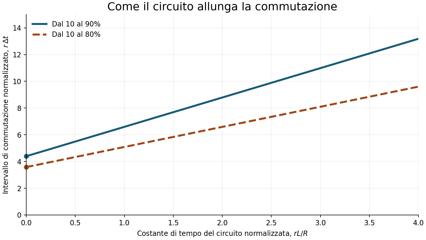
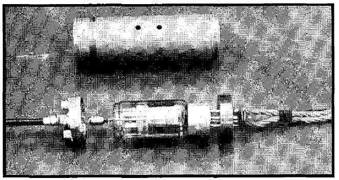
Figure 5 of the paper compares measured and calculated times with a 52 Ω load and series inductance reduced to a minimum. In figure 6, instead, the authors keep the supply at 3 kV and vary the external time constant. The two experiments test different aspects of the same equation. The photograph makes clear why they built an enclosure resembling a coaxial cavity. Shortening and suitably arranging the connections makes the term attributed to the tube observable. To apply this comparison to the 2D21 one would need its own waveforms, declared thresholds and an estimate of the inductance of the mounting.
The end of the current and the return of control
As the anode current falls the discharge can be extinguished, while the gas retains a residual population of charges. If the anode voltage returns too soon, the discharge can restart with a different threshold. In 1949 Wittenberg analysed the 2D21 and other types in pulse service precisely through the re-ignition potential after the discharge. A recovery time therefore makes sense together with the detection criterion and the sequence of applied voltages. Wittenberg, RCA Review, March 1949.
Test conditions and reading the chart
DC anode supply 125 V, anode current 100 mA, grid resistance 1 kΩ. The bars share the same origin and are proportional to the two times. The ratio 75/35 is about 2.14. Two points do not yield a continuous law of deionization.
Romanowitz and Dow examined the statistical nature and the physical concepts of deionization time. Hill dealt with plasma decay in high-repetition-rate tubes. An elementary diffusive representation uses \(N(t)=N_0e^{-t/\tau}\), with \(\tau\) linked to geometry and ambipolar diffusion. Summing several modes can describe decay phases with different scales. The operating time given by Sylvania indicates that a recovery criterion was reached in its test circuit. Identifying it directly with a constant \(\tau\) would require a measurement or a model linking the two quantities. Romanowitz and Dow, 1950 · Hill, Texas Tech thesis, 1978.
The typical anode drop of 8 V and the indicative ionization time of 0.5 µs given by the manufacturers are also reference points for different tests. To simulate a relay or a solenoid one then needs the load, the supply and the actual conduction time. To verify recovery, on the other hand, one must fix the way the discharge is extinguished and the voltage reapplied. GE, typical values · Sylvania, typical values.
1948–1949: the same type in timers and pulse service
The RCA application note AN-131 presents the 2D21 and 2050 as tubes for timers. It relates the low grid current to the use of high resistances in the timing network and exploits the fast transition to drive a relay. Wittenberg’s article of the following year instead documents tests of the 2D21 in pulse service and observes that its small size improved the frequency response compared with the 2050 in the test carried out. These are two complementary bodies of documentation: one concerns the grid drive, the other the history of the discharge and the repetition of pulses. RCA AN-131, 1948 · RCA Review, 1949.
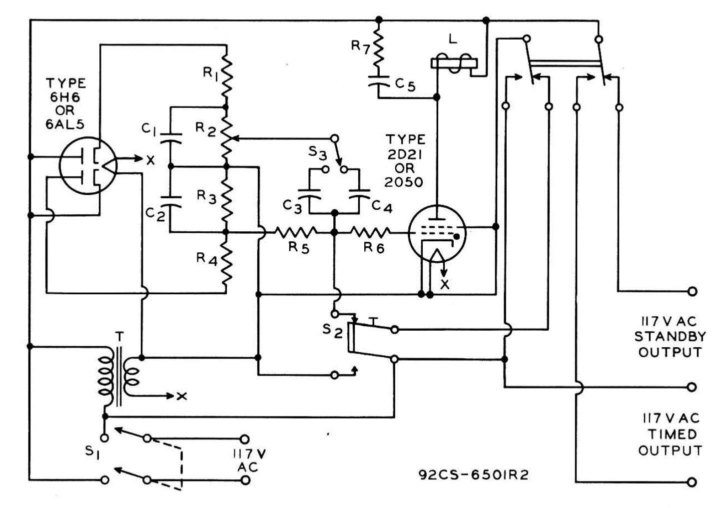
Figure 1 of RCA AN-131 includes a charging network and two time ranges, 0.3 to 3 s and 3 to 30 s. During charging the grid bias becomes progressively more negative. The passage through the negative anode half-cycle interrupts conduction and, at the following half-cycle, the grid voltage can prevent re-firing. This shows how an RC constant of the order of seconds and a much faster gas commutation can coexist in the same apparatus. The accuracy of the order of 1% mentioned by RCA concerns the timers described, with their supply conditions and components.
In figure 2 the note moves to a repetitive sequence with two tubes and a commutating capacitor between the anodes. When one branch fires, the capacitor lowers the voltage of the other and allows its grid to regain control. Figure 3 extends the sequence to three steps. The archive copy includes an errata sheet dated 15 July 1948: in the text on p. 3 the two timing potentiometers are R7 and R11. A transcription of the schematic should also keep this correction. RCA, errata attached to AN-131.
The post-war reference works
The collection Pulse Generators, edited by Glasoe and Lebacqz in 1948, documents the role of gas switches in pulse generators. Knight’s experimental work of 1949 examines cathode emission, ionization, current growth, grid control and the factors affecting the service life of thyratrons. The contemporary notice distinguishes the paper, pp. 361–378, from the discussion, pp. 379–381. Glasoe and Lebacqz, MIT Radiation Laboratory Series, vol. 5 · Knight, Proceedings IEE, Wireless Engineer notice, entry 504.