

The 2D21 Thyratron: From Historical Curves to SPICE Models
One valve, three different problems. Before firing, what matters is the weak current drawn by the grid network. At firing, the question is which combination of voltages makes the discharge self-sustaining. Once the discharge is running, the anode current sustains a plasma that changes the grid characteristic once again. It is this sequence that makes the 2D21 an interesting case both for the history of electronics and for circuit modeling.
This article collects the state of the art that I reconstructed through a literature search in August 2026: the GE, Sylvania and Mullard datasheets, the RCA studies on control recovery, the pulse measurements of Olmstead and Roth and the SPICE macromodel by Zabb Csaba. Pages 1–12 organize the measurements, the physical interpretations and the questions still open; page 13 sets out the sources and the scope of the research; pages 14–18 take a close look at the individual studies, from the Zenith receiver to the experimental checks of the macromodels.
1. From the Flash-Matic to the physics of the 2D21
The Zenith Flash-Matic receiver offers a concrete problem. In the power and muting branches, the photocell signal acts on the networks of the 2D21s, which drive the solenoids. The service schematic connects G2 to its own network through 2.2 kΩ: reducing the tube to an ideal three-terminal switch would lose a circuit variable before even discussing delay or extinction. For the signal path, the interlock and the schematic values see the analysis of the Zenith receiver on Giux-Lab.


Four optical windows, three valves and two solenoids
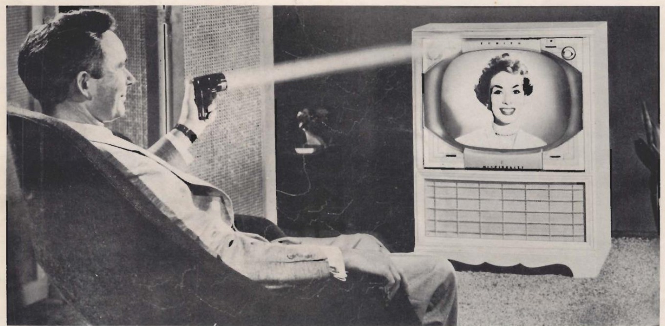
The Zenith manual makes it possible to follow a command from the light to the mechanical contact. The information lies in the illuminated position on the cabinet. The four cadmium sulfide cells change resistance with illumination. The manual gives up to about 100 MΩ in the dark and a value that can drop to about 25 kΩ under strong illumination. In between lie all the lighting conditions of the room. The sensitivity control R3 therefore sets how much margin remains between the resting point and the command threshold. Zenith, technical section, p. 4.
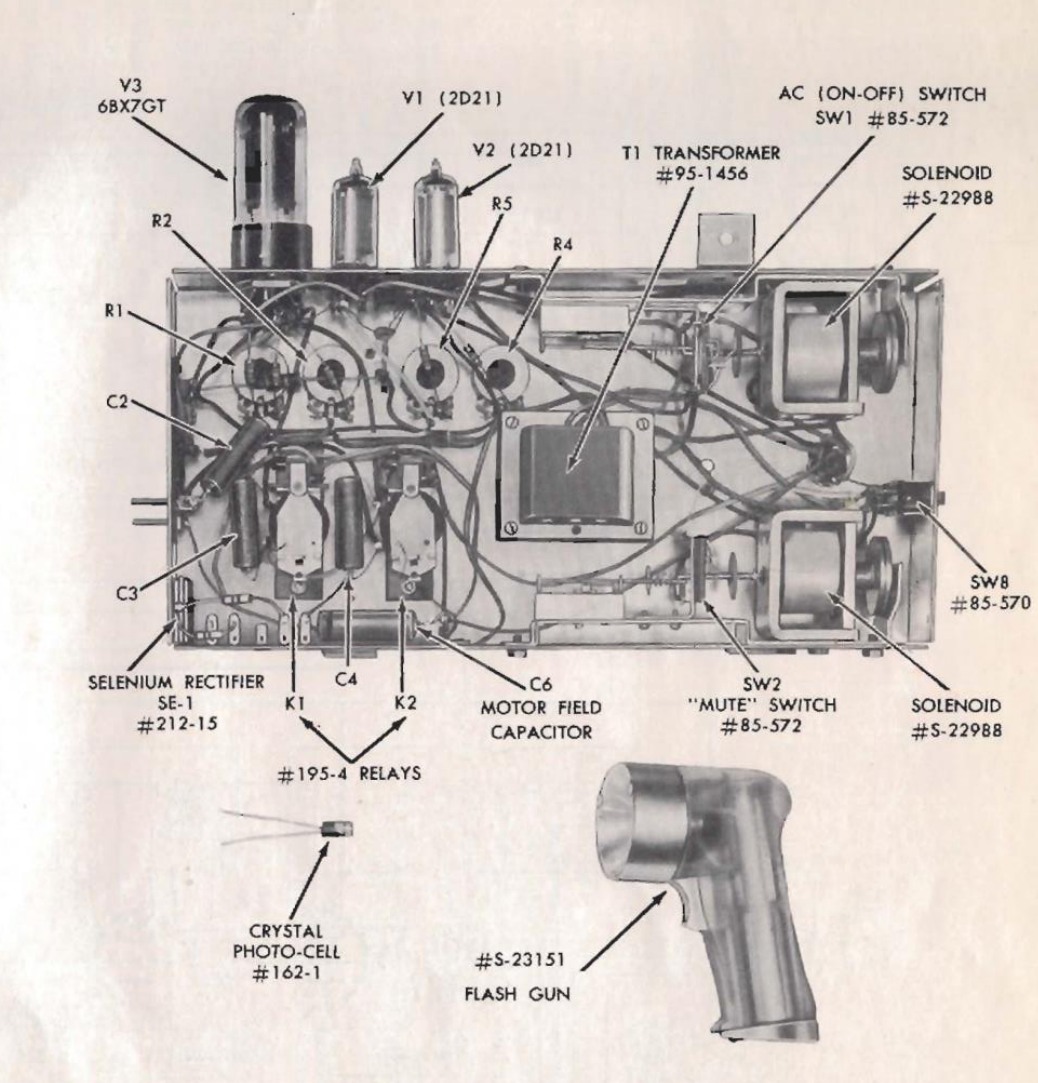
| Optical input | Valve in the receiver | Documented effect |
|---|---|---|
| PC-1 | V1 · 2D21 | The solenoid switches the television’s power supply. |
| PC-4 | V2 · 2D21 | The second solenoid switches the loudspeaker muting. |
| PC-2 and PC-3 | V3 · 6BX7GT | Relays K1 and K2 drive the two directions of the tuner motor. |
In the photograph you can make out precisely the two small bulbs above the edge of the chassis and, on the left, the taller tube of the motor control. The selenium rectifier and capacitor C1 provide the negative bias. The solenoid contacts prevent the two power branches from firing simultaneously. To simulate the response to light it is therefore also necessary to know the state of the contacts and the photocell resistance. A threshold voltage for the tube alone answers only part of the problem. Zenith manual, block diagram, fig. 2.
The gas tetrode and its electrodes
The 2D21 is a miniature inert-gas tetrode with a heated cathode. I use K for the cathode, A for the anode, G1 for the control grid and G2 for the shield grid. Electrode voltages are referred to the cathode unless otherwise stated. GE and Sylvania give G1 at pin 1, K at 2, heater at 3–4, G2 at 5 and 7 and A at 6. The figure of 0.026 pF between G1 and anode and that of 2.4 pF between G1 and the K–G2 assembly describe two distinct geometric measurements, relevant when the circuit drives a high-impedance grid. GE, description and pinout · Sylvania, p. 1.
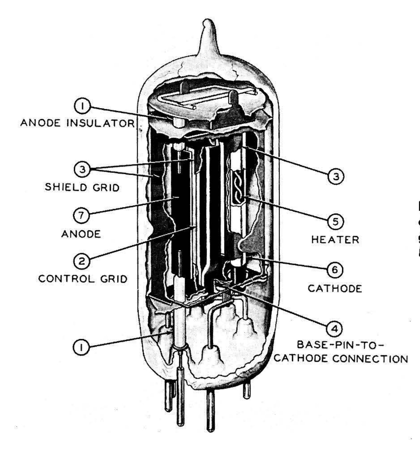
In the RCA drawing collected by Schure, the shield surrounds the cathode and the control grid. Two baffles guide the discharge through the structure. This geometry limits charge collection by G1 and explains why the grid can work with a very high-impedance source. The external connection of G2 nevertheless retains an electrostatic role. Its physical position and its electrical potential are two distinct aspects of the tetrode’s sensitivity. Schure, § 30, pp. 52–53.
The phenomena to be distinguished
| Phase | Quantities to observe | Evidence required |
|---|---|---|
| Before firing | Ig1, Vg1, Va | Families with no discharge and bias conditions |
| Firing | Vg1,crit, Va, Vg2, Rg | Control curves and the circuit with which they were measured |
| Conduction | Ig1, Vg1, Ia and A–K drop | Grid-current families and ON-state characteristic |
| Extinction and recovery | Residual current, bias and reapplication time | Waveforms and criterion for re-firing or control recovery |
These four phases answer different questions. A well-reproduced threshold can coexist with a wrong grid current. A good match of the conduction characteristics, on the other hand, leaves open the response to a short pulse. The review follows the historical measurements, the physical interpretations, the dynamic tests and finally the SPICE implementation.
For a close reading of the cited studies, pages 14–18 lead from the sources on the Zenith receiver to the recovery experiments and the SPICE macromodels. Each page opens with an index by author or document.