

Calibration Groups and Repeated Measurements
Curve Digitalizer can keep several calibration realizations for one and the same source image, distinguishing the active measurement, the draft, accepted or rejected state, and the measurements eligible for selection in Publish.
1. One Source for Several Calibrations
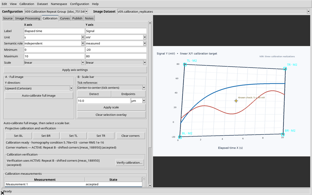
The test uses a single canonical Image Dataset image.raster, a synthetic 1280 × 900 pixel PNG with a quadrilateral graph, two colored traces and a control target declared at 5 s, 30 mV. The figure is not a real experiment; it serves to reproduce the calibration clicks in a controlled way.
After selecting the Dataset and the Preview source image → Use this image dialog, the test Digitizer Configuration V09 Calibration Repeat Group was created.
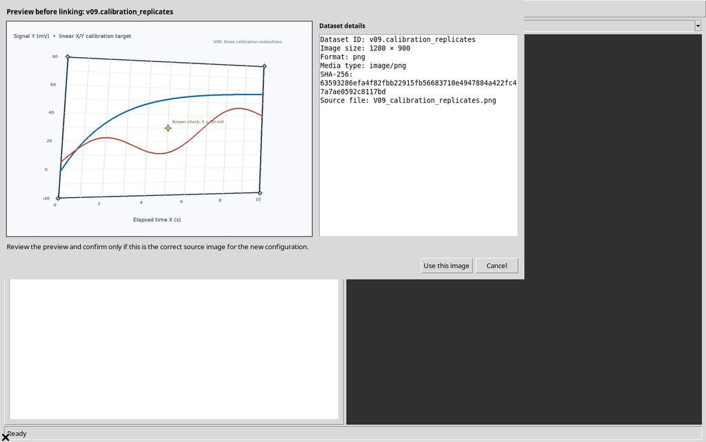
The traces in the PNG are not yet digitized canonical curves: initially the Session contains only an image and a configuration.
2. The Calibration measurements Panel
In the Calibration tab, below Projective calibration and verification, you find Calibration measurements: a table with the Measurement and State columns, single-row selection, its own scrolling and seven buttons:
New, Activate, Accept, Reject, Cancel draft, Rename and Delete.
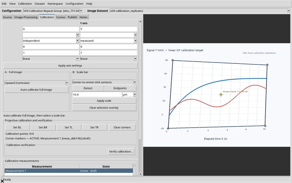
A new configuration normally contains Measurement 1, already selected and Active · draft. Its measurement identifier is assigned by the Viewer; the group has another, separate persistent identifier. These technical names are used to verify persistence and must not be edited manually.
3. Accept Does Not Accept an Incomplete Calibration
With the initial measurement still lacking the four corners, Accept was pressed. The GUI showed:
A complete four-corner calibration is required.
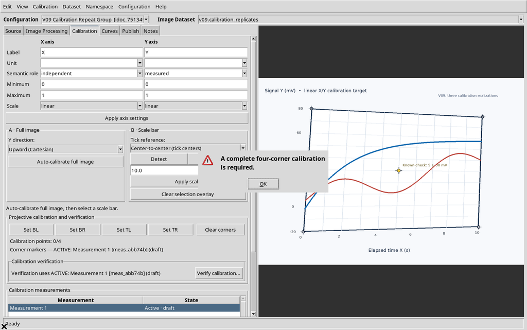
The Workspace state remained draft: a simple row in the table is not the same as a geometrically valid calibration. The same condition is required for a realization that will later be selectable in the Publish tab.
4. Protecting the Last Measurement: Cancel draft and Delete
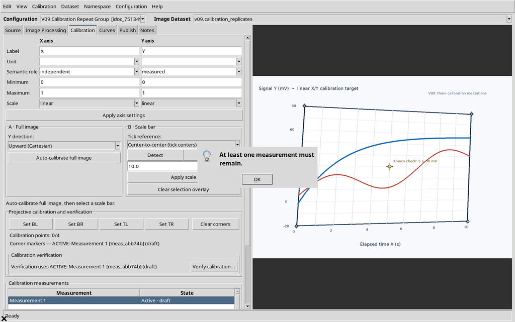
Two independent safeguards are shown on a configuration with a single measurement.
Cancel draft responded:
At least one measurement must remain.
Delete showed:
At least one calibration measurement must remain.
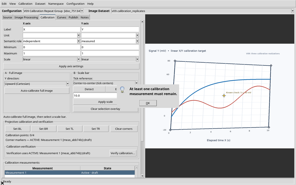
In neither case did the Viewer leave an empty group. The first measurement remained present, with the same ID and the draft state.
5. Setting the Shared Scientific Axes
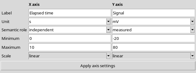
A linear scale was set with X Elapsed time, unit s, limits 0–10 and Y Signal, unit mV, limits −20–80. The data were applied with Apply axis settings.
The geometry of each realization is then recorded through Set BL, Set BR, Set TL and Set TR. When a new measurement is created, the limits and units already defined remain available as the basis for the new survey.
6. First Calibration: Four Real Corners
For the first realization the corners were acquired on the raster, using the four buttons and actual clicks on the canvas. The GUI showed the cyan markers BL · M1, BR · M1, TL · M1, TR · M1 and the status Calibration ready.
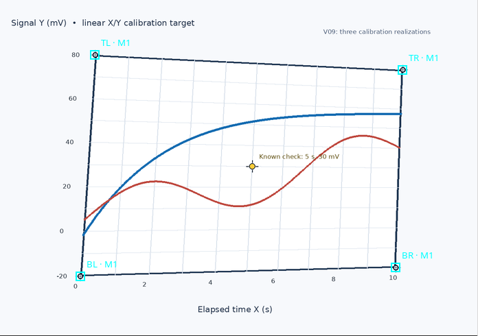
The four points represent the correspondence between source pixels and the normalized corners (0,0), (1,0), (0,1), (1,1) of the scientific surface. The transformation is projective, even though the numerical axes are linear.
7. Accepting Measurement 1
After the complete calibration, Accept changed the row from Active · draft to Active · accepted.
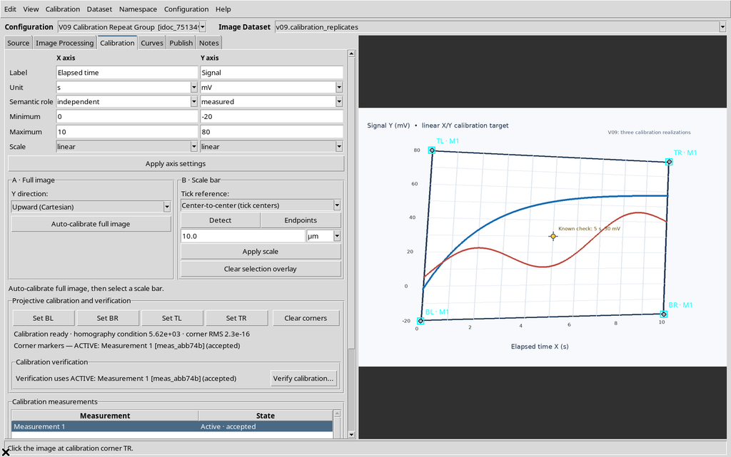
The framework keeps the same measurement_id, calibration_group_id, coordinates of the four corners and axes. Acceptance expresses an operational decision on the validity of the realization; it does not automatically introduce numerical uncertainty, nor does it publish Datasets.
8. New: A Second Measurement Without Deleting the First
Pressing New, the Viewer created Measurement 2, automatically activating it as draft. The current four markers were reset, while Measurement 1 remained accepted and kept in the same group.
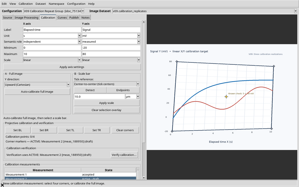
The Workspace therefore has two distinct IDs: M1 still contained its four points, M2 contains none. The scientific axis settings are inherited.
New does not delete raster points already digitized.
9. Selecting a Row Does Not Mean Activate
With M2 still active but incomplete, only the accepted row Measurement 1 was selected. The table highlighted M1; however, the text Corner markers — ACTIVE still indicated M2.
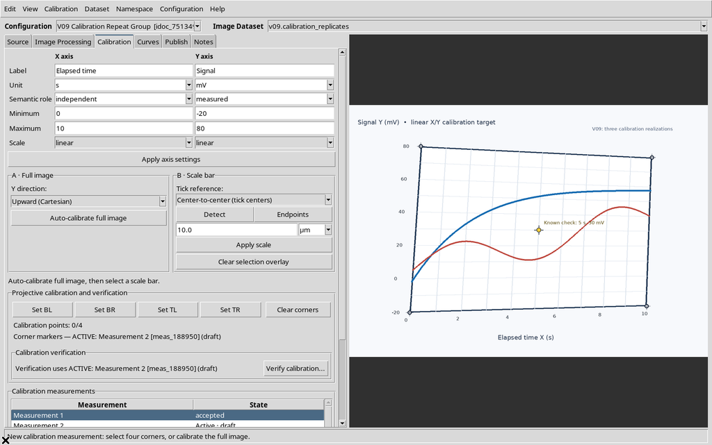
Verify calibration… was then pressed. The viewer refused the verification because the calibration was incomplete:
Complete the four-corner calibration and valid scientific axes before verifying a known point.
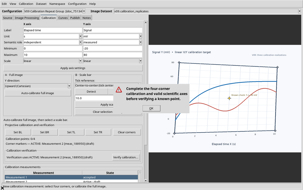
This matters: Verify calibration uses the active realization, not simply the highlighted row. The selection and activation functions are deliberately different.
10. Activate: Restoring the First Transformation
With M1 selected, pressing Activate brought back the four markers of the first calibration; the accepted measurement became active again and the second one remained saved as a draft without points.
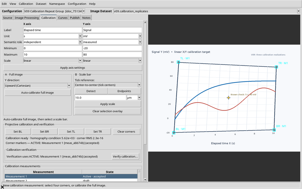
The interface did not recreate the image, and the CORE reloaded exactly the corners already persisted. To continue the second measurement, simply select M2 and press Activate.
11. A Second Realization with Slightly Shifted Corners
On the same image, M2 was completed with four new clicks slightly different from those of the first realization. Instead of assuming the same transformation, the Viewer kept a second, genuinely distinct homography.
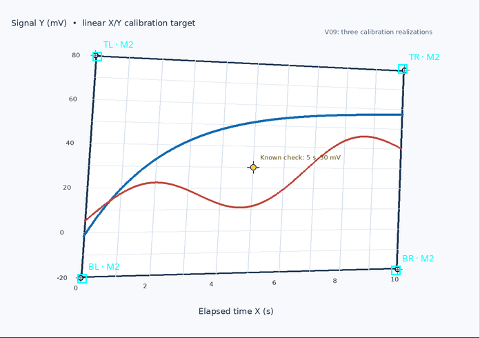
The group thus had two complete realizations, separated by ID and point coordinates but with the same X/Y ranges.
12. Two accepted Calibrations of the Same Raster
With Accept, the second measurement was approved as well. The table showed Measurement 1: accepted and Measurement 2: Active · accepted.
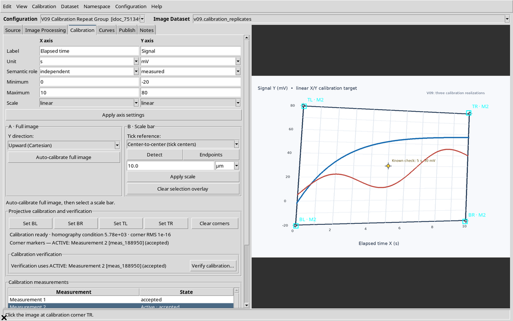
The difference between the two transformations is demonstrated numerically on an independent point later in the chapter. Accepting two calibrations does not mean claiming that the two surveys are two independent physical experiments.
13. Rename Keeps the Scientific Identity
The Rename command on the second row opened the native Rename calibration dialog, with the Measurement name field.
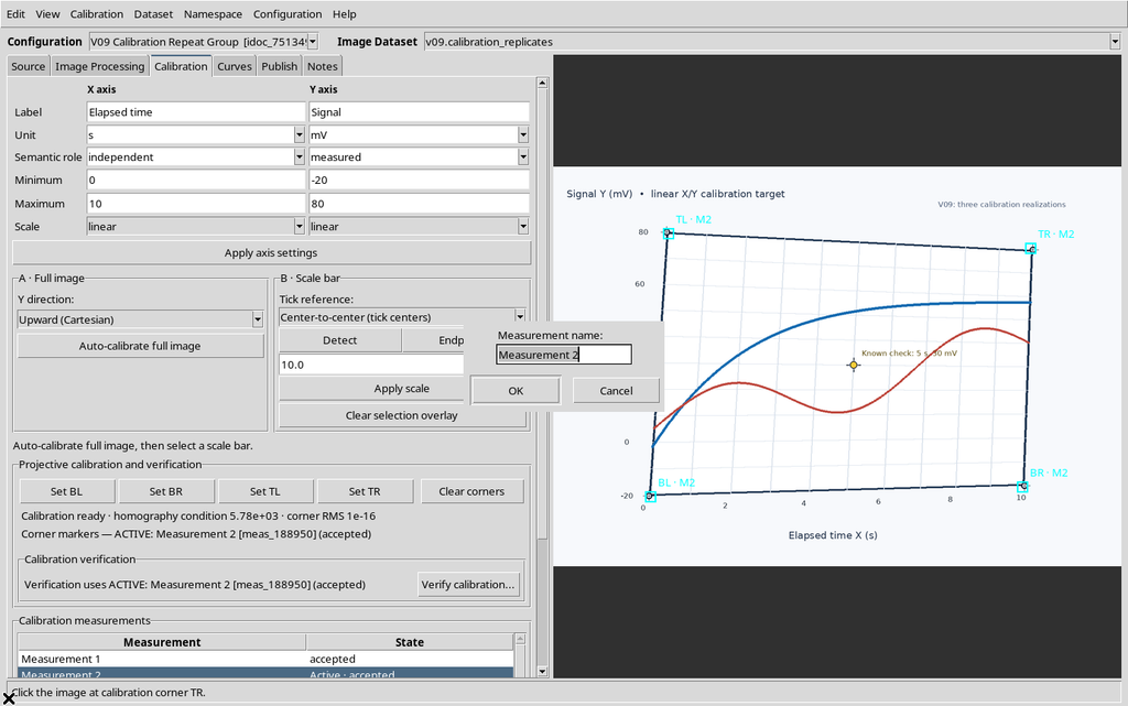
The new name assigned is Repeat B – shifted corners. The table and the text of the active realization were updated.
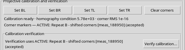
14. Third Realization: Complete Calibration but rejected
A third measurement was created and four new corners were selected, again on the same image, with the same pair of linear axes.
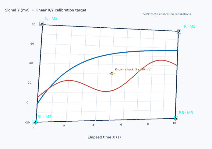
The Reject command changed the state to Active · rejected.
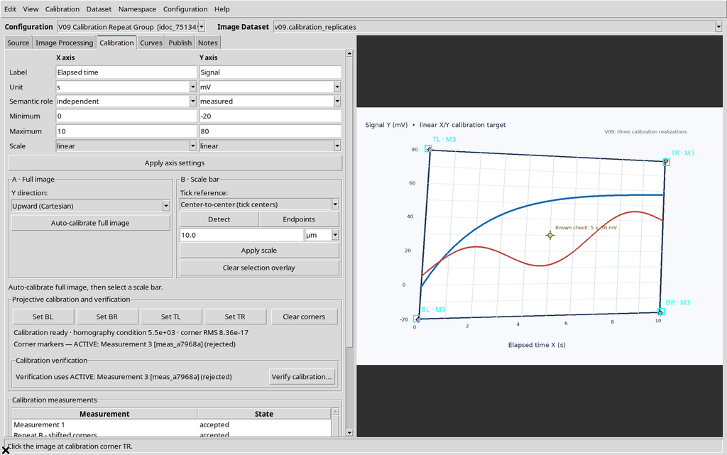
The rejected measurement remained in the group, with its ID and four corners. Reject is not the same as Delete. Its transformation can still be computed mathematically, but by default it does not belong to the set of measurements eligible for publishing.
15. Cancel draft Works Only on Drafts
Pressing Cancel draft while the rejected measurement was selected, the Viewer showed:
Only draft measurements can be cancelled. Use Delete for an accepted measurement.
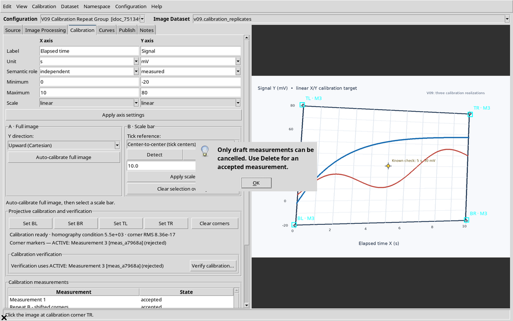
The same behavior occurs on a measurement that is already accepted. The interface prevents a button designed to discard drafts from accidentally destroying realizations in other states.
16. Only Accepted Measurements Are Eligible in Publish
Switching to the Publish tab, the Select accepted calibration measurements section contained exactly two rows: Measurement 1 and Repeat B – shifted corners. The third, rejected measurement does not appear, even when it is the active measurement in the Calibration tab.
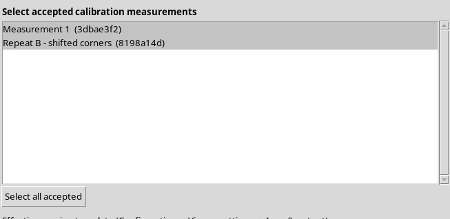
This confirms a second essential distinction: the active measurement determines the current mapping in the Viewer, while the selection for publishing admits only accepted realizations.
The GUI offers separate and combined in the Publication layout field; the numerical structures, the calibration_key, the columns and the scientific Preview will be verified in the dedicated chapters.
17. The Accept/Reject Decision Does Not Force Activation
After activating M1, the third, already calibrated measurement was selected. Accept moved M3 from rejected to accepted while leaving M1 active.
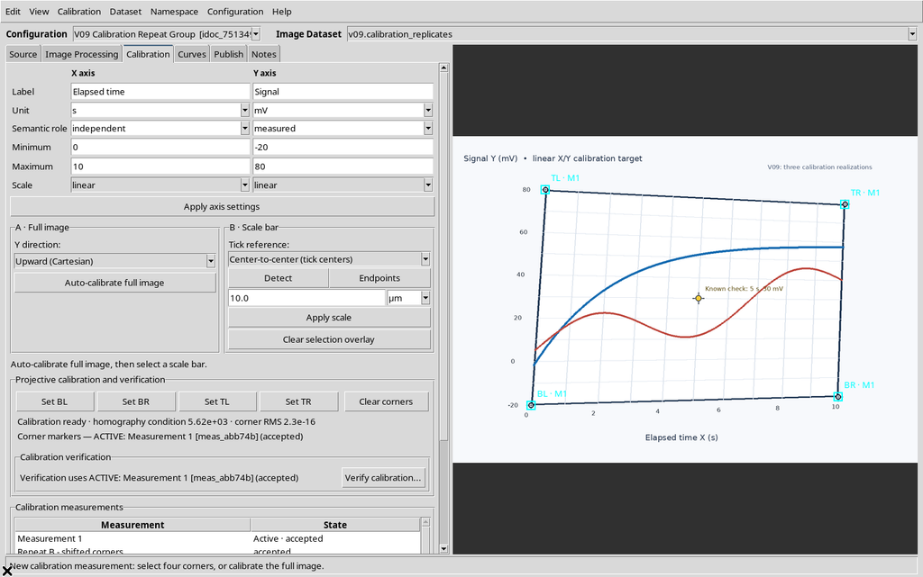
A subsequent Reject restores the rejected state, again without changing the active measurement or the stored calibration points.
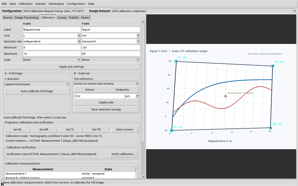
It is therefore possible to review the classification of a realization without silently swapping the scientific transformation in use.
18. Cancel draft with No/Yes Confirmation
To verify discarding drafts only, a fourth temporary measurement, Measurement 4, was created, active and with no new corners.
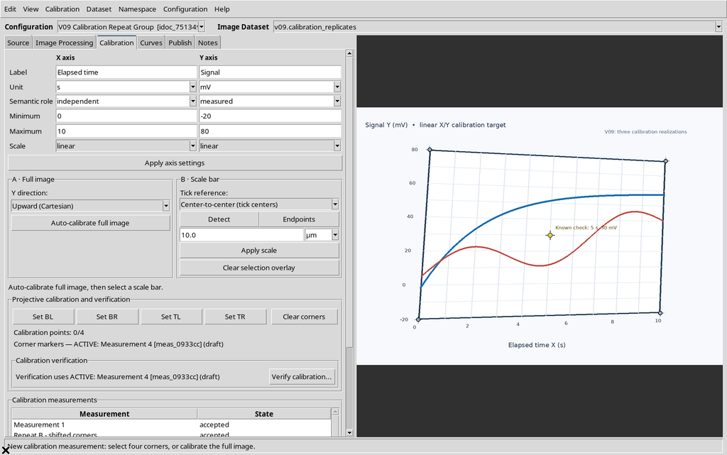
Pressing Cancel draft, the Viewer asked for explicit confirmation:
Discard draft ‘Measurement 4’?
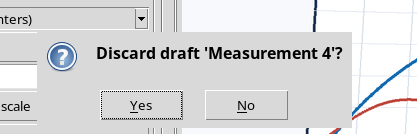
Choosing No kept all four measurements. Repeating the command and choosing Yes, only the M4 draft was removed; the program reactivated M1, accepted and available.
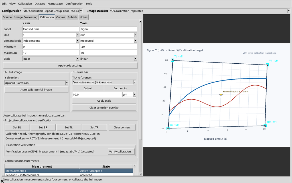
The two accepted measurements and the rejected measurement remained unchanged. No canonical source was deleted.
19. Delete: Confirmation and Persistence of the Group
Another fourth temporary measurement was created to show Delete separately. The command showed:
Delete Measurement 4 permanently?
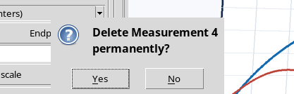
Choosing No left the measurement in place. With a second request and Yes, the Viewer removed only M4, preserving the group and the three previous realizations.
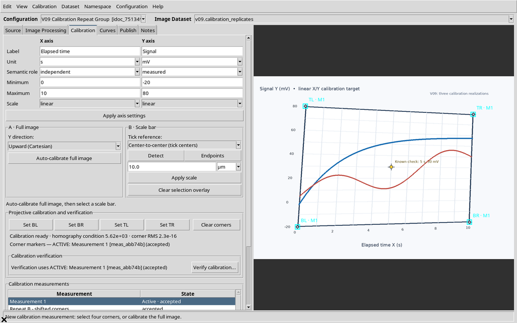
20. Same Pixel, Two Scientific Coordinates
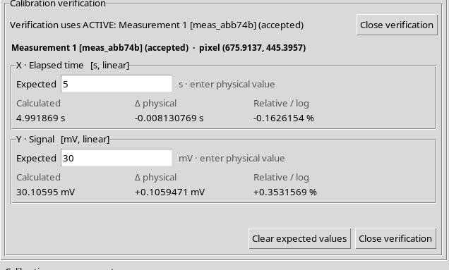
To compare M1 and M2, the same point of the raster was clicked at the identical canvas coordinates (367,379). The resulting source pixel was about (675.9137; 445.3957).
With Measurement 1 active and the known reference Expected X=5 s, Expected Y=30 mV, Verify calibration… returned:
Repeating the same click with Repeat B – shifted corners active:
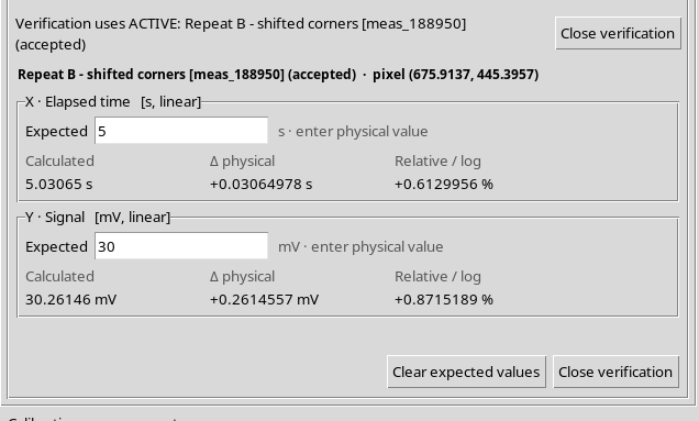
| Accepted measurement | Calculated X (s) | Calculated Y (mV) |
|---|---|---|
| Measurement 1 | 4.991869 | 30.10595 |
| Repeat B – shifted corners | 5.030650 | 30.26146 |
| Difference M2−M1 | +0.038781 | +0.155509 |
The second realization changes the pixel → science mapping, not the PNG pixels.
The differences are not automatically a standard deviation or a metrological uncertainty: they are two evaluations of the same raster with different calibration pointing.
21. Selecting the First Row with the Second Measurement Active
At the end of the numerical comparison, Measurement 1 was selected in the table without pressing Activate. The Viewer kept showing the cyan M2 markers and the text ACTIVE: Repeat B – shifted corners.
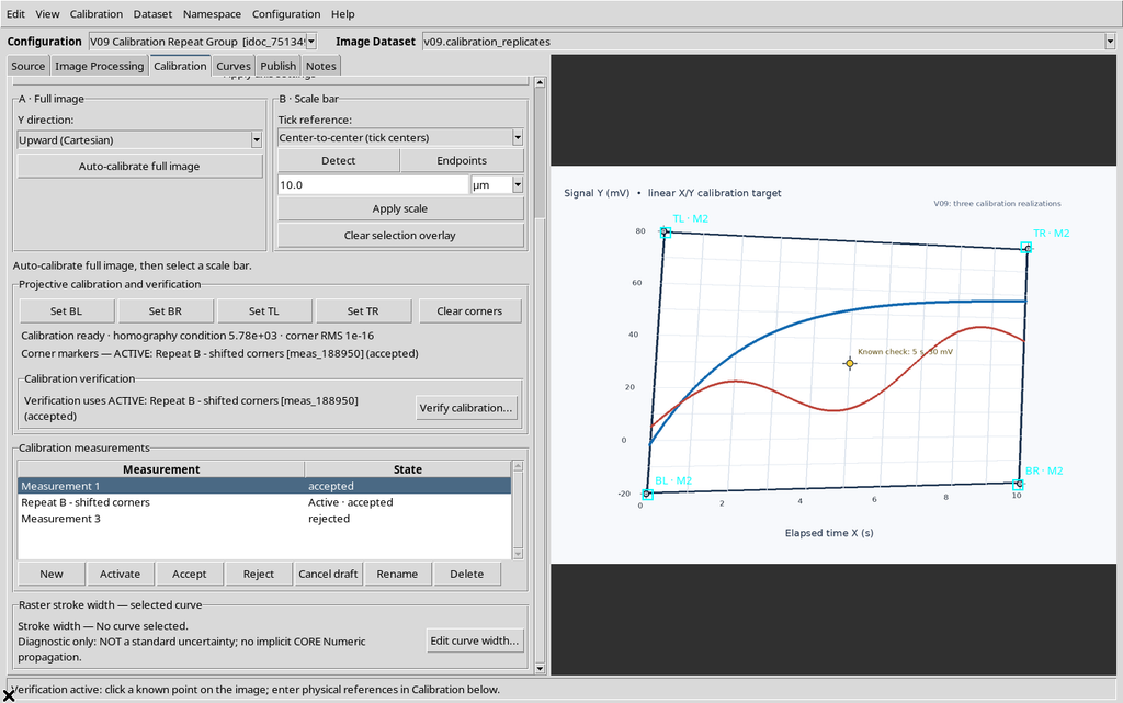
The numerical verification and the display of the markers depend on the active realization, while some table actions, such as Rename, Accept, Reject and Delete, operate on the selected realization. Always check the ACTIVE text before interpreting data or verifications.
22. Selection for Publishing and Two Possible Layouts
In the Publish tab, Select all accepted was pressed. The two eligible rows were selected, while the rejected one stayed excluded.
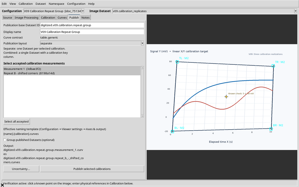
The GUI shows the choice Publication layout: separate / combined. The interface describes separate as one Dataset per calibration, and combined as a single Dataset with a column identifying the calibration. In V09 this is an observation of the presentation plan: Publish selected calibrations was not invoked and there are no new canonical tables to compare.
23. The Complete Table After Scrolling
The Calibration tab is scrollable. Scrolling it down, the Calibration measurements table shows all three rows with their final states and the whole bar of seven buttons.
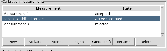
The calibration frame and the measurement table have different functions: the first manages the corners of the active realization, while the second determines which measurement is selected, activated, classified or removed. The frame also has its own independent internal scrolling.
24. Save, Close and Reopen in the Same Session
The final configuration was saved with Configuration → Save configuration, closed through the normal window protocol and reopened from the Viewers → Digitalizer catalog.
The framework contains a single canonical image, a single calibration group and the three final realizations:
| Label | State | Stable ID | Corners |
|---|---|---|---|
| Measurement 1 | accepted | Distinct | 4 |
| Repeat B – shifted corners | Active · accepted | Distinct, preserved after Rename | 4 |
| Measurement 3 | rejected | Distinct | 4 |
25. What Repeated Measurements Mean Scientifically
The three realizations are different choices of the four calibration points of the same digital graph. They are not independent experiments performed with a different instrument or sample.
The group keeps the IDs, transformations, axes and states. According to the installed model, the measurement ID is distinct from any fingerprint of the transformation; two geometrically identical mappings can belong to measurements with different IDs.
No variance, standard deviation, covariance or physical acquisition errors are derived automatically from these calibrations. It is possible to study the sensitivity of the calculated values to corner pointing, but a metrological assessment requires additional, declared assumptions and tools.
26. Short Operating Procedure
To study several calibrations of the same raster: define the axes, acquire four corners for M1 and check the geometry; press Accept. Use New to create M2, select four corners and accept it if suitable; repeat for further realizations.
Always check the difference between the selected row and the ACTIVE measurement. Use Activate when you want to change the current mapping and Verify calibration… to compare a known point. Reject keeps an unsuitable measurement; Cancel draft removes only a draft, with confirmation; Delete requires confirmation and cannot leave the group empty.
The Publish tab admits only accepted realizations, but the creation and structure of the Datasets will be verified in a later guide.